Vanagon Rear Brakes

By Ken Wilford

Why Vanagon Rear Brakes are Evil and How to make them Good…

Rear brakes on a Vanagon have probably driven me more crazy than any other part of the van. You can put all new brake parts on a van and if you don’t adjust the rear brakes properly your brakes will feel like crap. You can easily improperly install the rear adjusters so that they won’t work, and many of the springs in the rear only go a certain specific way or else they will jam up the adjuster as well. I have learned all of these lessons the hard way. Finally the rear drums can cause major pulsing pedal that you would think is coming from the front brakes because it is so pronounced.

My tips for best performance of rear brakes: Get as much new parts as you can before doing the job. You don’t want to get into the job and not have rear wheel cylinders, etc. that you are going to need.

Rear Drums

I’m not sure if it is really worth turning rear drums. If the drums look smooth on the inside and are within limits then I would clean them with brake cleaner and reuse them but if you have a pulse pedal suspect a bad drum. Replace drums only in pairs. If you have them turned be sure they are only turned in pairs and match each other’s diameter.

Look at the picture above and at the pictures in the Bentley Manual if you have had poor brake performance and compare it to what is installed on your van. Many times I have found parts improperly installed by a brake shop that didn’t know/didn’t care what they were doing. Pay particular attention to the springs that are directly below the adjuster and rear wheel cylinder. They are made so that the hooks grab the center tabs from underneath. This allows the adjuster to clear. You can easily install them upside down but this jams up the adjuster.

As for the adjuster itself it has two ends, both of which need to be installed properly. One end looks like a split boat paddle with one longer piece and one shorter piece. This end goes toward the emergency brake lever. The longer piece needs to get on the inside of the brake shoe metal plate (toward the backing plate) and the shorter side is out where you can see it. The other end looks like a squared off paddle that is much shorter and squatter. One side is square and the other side has a small notch cut out of it. The squared side should be out where you can see it and the other side with the notch out of it should be behind the brake shoe metal plate (toward the backing plate).

Final adjustment:

Once you have everything properly installed, the final adjustment is the key to getting a high pedal and also a good e-brake. Adjust the brake adjuster until you can’t slide the drum on any longer. Now back off the adjuster in five click increments until you can just put the drum on. You don’t want to have to force it on that is too tight. But when it is on you want to hear a dragging noise when you turn it and also a little bit of resistance. Now go inside and try the e-brake cable. It should only pull up three or four clicks. If it goes higher then you still need to adjust the shoes out a bit farther. Put drums on and then try the pedal. It should feel hard and high. If not adjust some more.

That is it. I properly adjusted set of rear brakes will give you great e-brake, smooth braking and also a high pedal that feels great!

Vanagon Front Shifter Removal and Replacement

By Ken Wilford

You can use this guide to remove your shifter if it is broken or you are just pulling it to install new bushings, etc.

  1. Drop your spare tire under the van. You will see a box directly below where the shifter is located.
  2. Remove the 4 10mm nuts holding it in place and remove it.
  3. Now you will see the bottom of the shaft. There is one bolt going through the bottom of it. Remove this. (10mm wrench and socket or 2 wrenches)
  4. Go back into the cab and pull the rubber boot back from the floor.  You will see the mounting plate where the shifter is mounted to the floor.  It has two holes in it.  Mark these with some white paint so you can put the shifter back exactly the same orientation as the old one.
  5. Now you can go up into the cab and pull the whole shifter up and out of the car as one unit.
  6. Put your new/used one back in the reverse of how you did this one. Be sure to line up the mounting plate holes with the paint marks you made and your shifter alignment should be the same as it was.

Vanagon Ignition Switch Replacement

By Ken Wilford

Here is how to remove and replace your Vanagon ignition switch.

1. Unscrew the two retaining screws for the bottom steering column plastic cover and remove it.

2. Pop the cover off of the center of the steering wheel by gently pulling it toward you and once it is removed, unplugging the horn wires.

3. Undo the nut that holds the center of the steering wheel on (a large one- 24mm?).

4. Mark the steering wheel with a marker on the metal that is around the center and the center shaft so you can put it back exactly as you removed it.  I use a line so you can just line the two parts back up.  Now remove the steering wheel, it will just pull toward you and come off without a puller.

5. Reach around the column and unplug the plugs for the ignition switch and the wiper, blinker switch, etc.

6. Insert your key into the ignition and turn it to “on” position.

7. Undo the allen bolt that holds the ignition switch housing to the column.

8. Undo the slotted screws that hold the blinker/wiper arms to the assembly and remove the arm assembly.

9. Gently pry the plastic the center spacer off the central shaft.  I go back and forth with a large flat head screw driver until this can be removed without damaging it.

10. Pull the ignition switch housing toward you off of the steering column.

11. Ignition switch will become accessible now with a small phillips head screw driver from the rear.

12. Reinstallation is reverse of removal 🙂

How to remove and replace Vanagon Brake Booster

By Ken Wilford

I thought I would write this up as I just did this one today.

1. Remove cover on instrument cluster and plastic dust cover.

2. Unplug everything and remove the instrument cluster

3. Place something on the floor of the van to catch any brake fluid that will spill out (rags, a pan, etc).

4. Unhook the two steel brake lines on the brake master cylinder with a 11mm wrench.

5. Unplug the rubber feed hose that goes from the brake fluid reservoir to the clutch master cylinder.

6. Undo the two 13mm nuts that secure the brake master cylinder to the booster and slide the MC out. Stop here and you have the removal for just the MC. (Easy).

7. Remove the steel line that attaches to the clutch master cylinder (12mm wrench).

8. Undo the two 13mm bolts that hold the clutch master cylinder and pull it down until it comes out. Stop here and you have the removal of the clutch master cylinder.

9. Remove plastic pieces under steering wheel and under dash around the area of where the booster is.

10. Remove the four 13mm bolts that secure the booster bracket to the firewall (there is one in each corner).

11. Unhook the two bolts that hold the steering column to the dash. Also unhook the two 10mm bolts that secure the other end of the two steel straps that are above the brake booster.

12. Move the two steel straps out of the way.

13. Pick up on the booster and you will get a better look at the rear of it. The pin that holds the booster linkage to the pedal linkage is secure with a cotter pin on the driver’s side.

14. Remove cotter pin and push retaining pin releasing the booster linkage from the pedal linkage.

15. Unhook the four 13mm bolts that hold the booster to the aluminum pedal mount.

16. Unhook the vacuum line on the brake booster.

17. Pick the booster up and out of the dash.

Installation is the reverse of removal. Please print this out and put it in your Bentley. Feel free to offer suggestions to make this How-to better.

How to Remove and Replace Brake Pads on 86-91 Vanagon

By Ken Wilford

A quick how-to on changing brake pads on Vanagons with Girling Calipers (’86-91 including Syncro).

1. Place van on level, hard surface

2. Chock the rear wheels or put on the emergency brake or put it in park.

3. Jack up van (I used the jack that came with the van)

4. Remove the wheel.

5. Remove upper Caliper bolt that is on the backside of the caliper (hold guide pin with 17mm wrench and remove bolt with 13mm wrench).

6. Loosen lower caliper bolt

7. Swing caliper down out of the way.

8. Remove old brake pads.

9. Crack caliper bleeder screw. (7mm wrench)

10. Use a clamp to compress caliper piston (a 6″ wood clamp will work by placing the body of the clamp against the back of the caliper and the screw side against the rim of the caliper piston. Now tighten the clamp until the piston is almost completely compressed- brake fluid will squirt out so have something to collect it with).

11. Before removing the clamp, close the bleeder screw (this minimizes the amount of air that gets into the system).

12. Place new pads in place of old ones.

13. Swing the caliper back over and align with guide pin.

14. Reinstall guide pin bolt and tighten (see Bentley for Torque Values)

15. Replace wheel

16 Lower van

17. Do brakes on the other side in the same manner

18. Lower the van

19. Fill the brake reservoir to Max.(You will find the reservoir under your instrument cluster cover.)

20. Bleed the brakes (have someone pump up the brakes and hold the pedal down. Crack the brake bleed screw on the caliper and you will hear the air and brake fluid squirting out. Have something to catch it in or you will have a mess on your hands. Now with your friend still holding the pedal down close the bleed screw. Repeat this process as many times as is needed to remove all air from the system. Repeat on the opposite side caliper.)

21. Fill the brake reservoir to Max. Do this at your own risk, disclaimer, legal blah, blah, blah.

I crack the brake bleeds and compress the caliper rather than just compressing the caliper piston in order to prevent crap from being forced back up into the brake master cylinder. If you don’t do it this way you could be doing your master cylinder in.

VW to NAPA Part Number Coolant Hose Conversion Chart

VW to NAPA Coolant Hose Conversion
for many ’86-’91 Vanagons
By Darrell Boehler

This conversion is based upon NAPA brand hoses that were either exact replacements for, or adapted to replace their VW counterparts. The conversion was performed on a 1986 VW Vanagon Westfalia with 2WD, manual transmission, and air conditioning. Your mileage may vary.


Coolant Hoses
Wasserboxer 86-91 2WD


Heater hoses are all 5/8″ hose and no big problems. I replaced the T’s for the rear heater with 5/8″ diameter T’s on all three points because the originals had two 5/8″ and one 1/2″ point. 30′ of 5/8″ hose is needed to replace all heater hoses. Straight hoses will even make the turns for the front heater under the dash without too much problem. However if your inside front heater hoses are good I would consider keeping them as they require a bit of time to replace. I was considering connecting my heaters in series instead of parallel, but backed off because I thought it might degrade the heat. NAPA has regular grade or premium grade heater hose and so do many other stores.

Simple Conversion


Hose:
VW Part #: NAPA Part #: Description: Dimensions:
D N902873.03 1.5″ hose* Valve to radiator feed.
F
251-121-058a 1″ hose* Thermostat housing to valve. 1″ ID about 2ft long
G 443-121-107A This is a 7mm hose from a VW FLAPS, NAPA here doesn’t carry 7mm hose
H 252-121-130b 7990 Right head front to valve.  1″ ID, 6″ long. Has 2 60 degree bends
J 025-121-058e 10050 Thermostat housing to oil cooler pipe .472″ ID one end, other end .635″, 3″ long
K
025-121-058D Oil cooler to oil cooler pipe from from thermostat housing. No direct solution here. However 5/8″ heater hose about 2 feet long can be run directly from the oil cooler to the thermostat housing eliminating the need for hoses J and K. I like the one hose solution better than the normal path as there is more clearance from the oil cooler hose and the header pipe. My hose K got brittle and blew coolant all over my clean engine.
L
025-121-058G Oil cooler to oil cooler pipe from water pump. No NAPA hose replacement and no good way to eliminate this hose that I have found. Maybe someone else can find a sub.
M
025-121-058J 3/8″ ID hose A straight hose will function fine here 3/8″ ID 4″ long
O N901287.03 1″ hose* Water pump feed to right side of crankcase. 1″ ID 3″ long
P
443-121-107A 7mm VW FLAPS. Right head to pipe
Q
025-121-108D No NAPA solution. Pipe at water pump to expansion tank. This hose is designed to take a lot of flexing between the engine and the expansion tank. I need help on this one, somewhere there must be another application that uses a similar hose. 1″ ID one end, 3/4″ ID other end
R 025-121-058h 9807 Expansion tank to pipe tee .620″ ID both ends. 90 degree bend each leg 4.5″ long
S 025-121-058B No NAPA solution. Thermostat housing to pipe tee. Need help on this one also. 1/2″ ID one end 7mm other end, about 14″ long.
? 025-121-073H 777 Thermostat housing to water pump pipe. This hose doesn’t seem to be listed on the chart. Good picture of it in Bentley on 19.11. It is the big one there with the 90 degree turn. 1.5″ both ends 90 degree bend 1 leg 6″ other 4″


* I got a 3ft long heavy duty NAPA hose and cut it to fit

For the rest of the hoses I used copper pipe, 90 degree elbows and various copper pipe adapters. This requires soldering some pretty heavy pipe but could be done with a plain propane torch. I bought NAPA heavy-duty hoses that are used mostly on diesel trucks and industrial applications. This was a mistake I would go with regular grade hoses if I did this again. The heavy-duty hoses has double layers of nylon reinforcement and outside wrapped with nylon. It is a real pain to work with and after a couple of days working with them I discovered why most Illinois diesel mechanics appear to be fresh off the Minnesota and Wisconsin farms. I used 6′ of 1.5″ ID hose, 3′ of 1.25″ ID hose, 3′ of 1″ ID hose. Most 1″ stuff was used in the previous table on F and O.

Complex Conversion


Hose: VW Part #: NAPA Part #: Description: Dimensions:
A 251-121-082 1.5″ and 1.25″hose Upper radiator feed hose Radiator connection is 1.33″ and long hoses are 1.5″, straight 28″ long. I used some 1.25″ hose at the radiator end and made an adapter using 1.25″ copper pipe, adapter to 1.5″ copper some 1.5″ copper pipe then 1.5″ hose to the long feeder hose.
B 251-121-083H 1.5″ and 1.25″ hoses Lower radiator return hose Same ID on hose as A above however 3 90 degree elbows are required on this one. Use a short 1.25″ hose, a short 1.25″ pipe, 90 degree elbow toward the rear a short 1.25″ pipe (make this pipe just long enough to get aft of the radiator and radiator holder bracket), 90 degree elbow pointing up and slightly to the left, enough 1.25 pipe to get up high enough to get over the spare tire, a 1.25 90 degree elbow pointing toward the rear, some 1.25″ pipe, an adapter to 1.5″, some 1.5″ pipe then 1.5″ hose to the radiator return long pipe.
E 025-121-062E 1.5″ hose and some 1.5″ copper pipe Return to thermostat housing 1.5″ both ends however this one goes up and over the transaxle. Use a short 1.5″ ID hose about a 2.5 inches of copper 90 degree up, about 10 inches (check this measurement) 1.5″ ID copper pipe up line these up so your copper pipe rests nicely in the hose holder above the transaxle), Now 90 degree copper elbow and you are heading over the transaxle, install enough 1.5″ copper pipe so you line up with the thermostat housing. (hint it is best to be a little too long with the pipe going over the transaxle or your hose might cause shifting problems). Now turn 90 degrees with copper elbow toward the thermostat housing install a short 1.5″ ID pipe in the elbow. use a 1.5″ ID hose to connect to the thermostat housing. That sounds pretty involved, try this for directions from the long return hose go back a few inches up about 10 inches over the transaxle about 20 inches and turn back toward the thermostat. What you end up with is a copper pipe with three 90 degree elbows attached.
N 025-121-058M Gates 20693 hose, home made adapter and some 7mm hose Left head to pipe One end is 1″, the other is 7mm. Start with a Gates 20693 hose (which is a 1″, 90 degree hose). I then used an adapter from my local hardware store from 1″ down to 1/4″ ID copper pipe that I used and then just stuffed the 7mm hose over that. The original hose on my 86 had sprung a leak and for a while I thought I had a head leak. Thanks Malcolm Stebbins.


Manual Transmission Drive Flange Seal Replacement for Vanagon

By Jim Felder

Time: about four hours

Tools: nothing special in a modestly-equipped shop. Assumes you have a

small cheap inertial puller set.


Do one side and then the other. In both cases:


  1. Jack up the first side, chock the other. release the emergency brake

and then put in neutral. You’ll need to lock up either the wheel and

other times turn it (to remove and tighten the CV joint bolts) or the

flange itself (for circlip removal/refitting) at various stages of this

procedure.


  1. remove the allen-head bolts holding the inner CV joint to the

transmission flange. Clean out first with a small pick, then tap in

allen wrench with a small hammer to ensure seating in the fastener.

Otherwise, you risk rounding out a bolt.


  1. Drop and bag the CV joint for cleanliness. Have some good moly

greasy on hand if it needs repacking.


  1. You’re looking at the flange. Talk a hammer and a sharp tool and

drive it into the plastic plug in the center of the flange and pry out.


  1. Remove the C-clip with two screwdrivers, better a screwdriver and a

hook tool like a spark plug boot remover.


  1. Use a 3-jaw puller to remove the flange.


  1. Remove the two phillips screws that hold the plastic dirt shield to

the transmission.


  1. Clean everything you removed by soaking in gasoline, be sure you get

the spring washer from inside the flange.


Now you can see the seal in it’s aluminum housing.


  1. Use a sharp-pointed tool east and west positions on the seal itself

and punch holes.


  1. Use the screw tool with the puller to screw into the holes you

punched in the seal. There’s a big old ball bearing behind the seal,

don’t worry about it. Keep turning the puller screw into the seal

housing until the pressure of the screw point against the bearing rides

the seal out of its home. When you tighten the puller screw with a

wrench, you’re stopping the screw point against the bearing and riding

the seal up the threads and out of its seat.


  1. Oil up a new seal with transmission grease and tap home with a

stick, dowel or rod about 1/2 inch diameter and about 8 inches long.


  1. Tap flush with seal housing, keeping tapping constant while moving

rod or dowel constantly around seal housing.


  1. Remove soaking parts from gasoline and clean.


  1. Refit plastic dust cover and screws and then refit flange. Protect

with section of 2 x 4 and wail away with hammer until seated.


  1. Refit spring washer cup out (center part the closest to you).


  1. Refit clip ring with two medium flat screwdrivers. The first time

you do this, it will take about ten minutes. The second time, about 30

seconds. There is a technique.


  1. After fitting clip on axle stub, tap clip into place with small

flat punch and hammer to make sure it is seated in the groove against

the pressure of the spring washer.


  1. Tap in new seal, smear joint with RTV adhesive.


  1. Refit CV joint, packing with grease if necessary.


  1. Repeat from step 1 for next side.


  1. Drop shift rod by removing upper and lower 13mm bolts and nuts.


  1. Remove transmission filler plug with 17mm internal socket.


  1. Fill transmission per Bentley.


  1. Replace filler plug.


  1. Lube shift cup and shift bushing with moly grease, replace bad

rubber as necessary.


  1. Rehang rear shift assembly as reverse of removal in step 21.


  1. It’s over

Engine Conversion- Diesel to Gas VW

By Tom Carrington
With the passing of my Bug in 1987, I was VW-less for several months until bought a 1980 Vanagon. What a wonderful vehicle! I am still hooked on those things today. I sold it after a few years to purchase another VW, this time a 1965 Notchback.

My 82 Westy Vanagon.

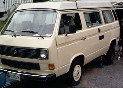
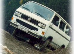
Today, I still own the Notchback, and now also have a 1982 Diesel-powered Westfalia Vanagon. This is a vehicle I have lusted over for several years.

Diesel engine.

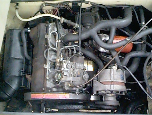
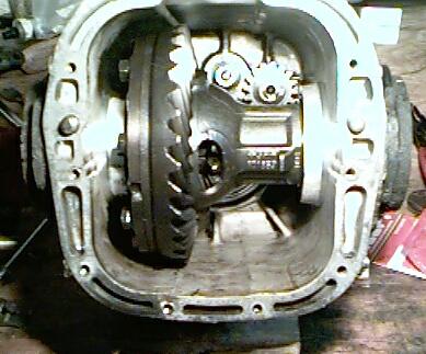
The main reason that I wanted this specific model was the engine conversion possibilities. This picture shows how the Vanagon diesel engine is basically the same engine as the Rabbit diesel, just tilted over on its side. And since the VW diesel engine is similar to a VW gas engine, I have always wanted to install a Rabbit/Golf GTI engine in a Vanagon.

Well, that project is now underway!

Saturday, October 26th, 1996:
Pic of hoistengine & trans out of Van

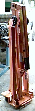
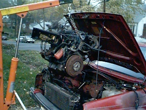
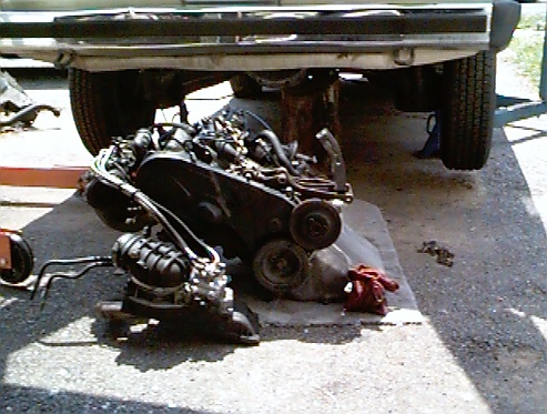
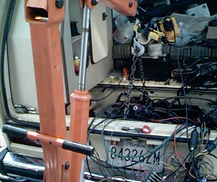
I removed the diesel engine from the Vanagon. I decided to remove both the engine and the tranny together as a single unit. The collapsible engine hoist that I bought from Harbor Freight Tools was a big help in removing the engine.

All told, it took me about 4 hours to remove the engine and tranny as an assembly, and separate them once out of the Vanagon. I also removed the muffler. If I had to do it again, I would remove the muffler while the engine was still in the car. I also removed the alternator just to get another spot to attach the hoist’s chain to.

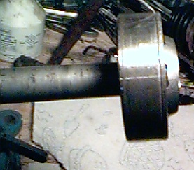
Another thing I noticed when removing the engine/tranny, is that the grease in the CV joints was nearly dry. I guess now will be the easiest time to service them. I plan on replacing all of the boots (even though they look fine, they are almost 15 years old) when I repack the joints.

Sunday, November 3rd, 1996:
Gas engine from 86 Golf hanging from hoist

I removed the gas engine from the donor 1986 VW Golf. Removal was pretty straightforward, with just some minor “persuading” so separate the engine from the transmission. Now the task of transferring parts (exhaust manifold, oil pump & pan, etc.) from the blown diesel engine to the gas engine can begin. I also plan on replacing the O-ring seals on the fuel injectors.

front view, looking into the bell housingside view of trans

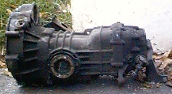
I also snapped a few pictures of the diesel 4-spd manual transmission. It is essentially the same as the gas-engined models, except it has different gear ratios, bell housing and input shaft. I will be swapping the bell-housing and input shaft over to a transmission from a gas powered Vanagon before re-installing the engine.

Sunday, November 10th, 1996:
Today I removed components from the diesel engine that need to be transferred to the gas engine. I also spent time degreasing the gas engine that will be installed. No cool pictures, though. 🙁

Saturday, November 16th, 1996:
Gas engine on a standGot a lot of work done today! I started by installing the oil pan & pump and exhaust manifold on the gas engine. I have decided to retain the stock diesel exhaust system, as opposed to fabricating a custom exhaust for the van. Exhaust manifolds
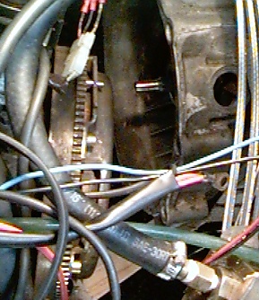
As you can see from the picture to the right, the diesel manifold (on the left in the photo) is quite different from the gas manifold. There is no doubt that the diesel version is much more restrictive than the gas exhaust. While this will probably hurt the performance slightly, it will make for an easier install. If I am not happy with the power after test driving, I might consider swapping then. I also replaced the fuel injector O-rings. The gas engine is looking pretty complete, and will be ready to install next weekend!

transmissionstransmissions
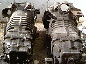
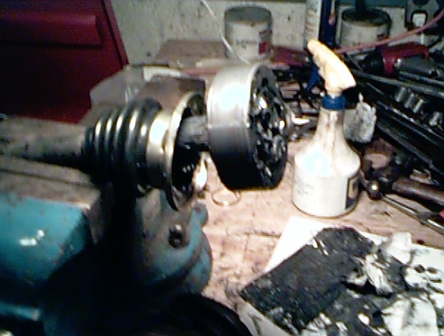
I also received a replacement trans from an early ’80s gas powered Vanagon. Fellow Vanagon Listmember, Ken Wyatt, found it in a salvage yard and shipped it to me for a very reasonable amount. Thanks Ken! I took some pictures of the gas and diesel transmissions side-by-side so the differences would be visible. Note the shapes of the bellhousing to accomodate the different engines & starter motor locations. On the diesel powered Vanagons, the starter is on the top of the trans, and on the gas models, it is down on the side slightly. The gas trans also has thicker and more pronounced ribbing on the case.

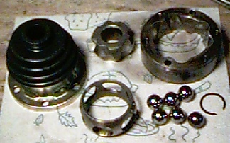
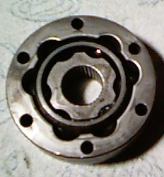
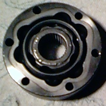
I also spent some time sevicing my Constant Velocity, or CV Joints. I took several photos and documented the process on Tom’s CV page.


March, 1998:


An issue with the engine conversion is the low gearing of the diesel transmission. The stock diesel engine output is 48 HP versus the 67 HP of the air-cooled gas engine offered the same year. To compensate, the diesel transmission has lower gear ratios than the gasoline transmission. At highway speeds with the diesel transmission, the engine rpm is quite high. To allow the engine to turn a little slower, I modified the gas-powered Vanagon transmission by installing the bell housing and input shaft from the diesel trans. The process is not too difficult, with only a few special tools needed. I tackled this part of the job during the Memorial Day weekend in 1997.

Transmission innards.

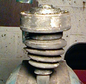
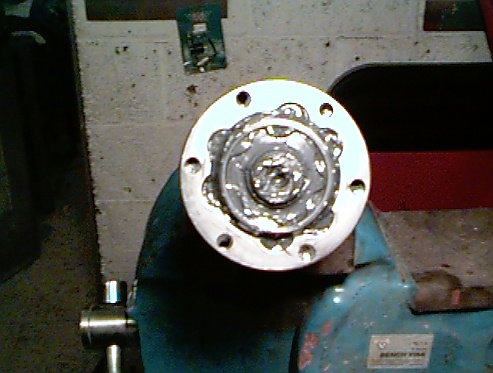
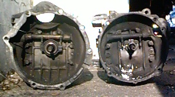
Start by draining the transmission. With the transmission on a workbench, simply unbolt the bellhousing from the transmission. The bellhousing will now slide off the transmission. The input shaft is secured with a small circlip retaining ring. Remove the ring, slide the splined collar/coupling out an inch or so, and unscrew the input shaft. After removal of the input shaft, the tranny will look something like what you see on the left.

Shaft closeupInput shafts.
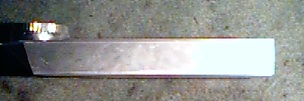
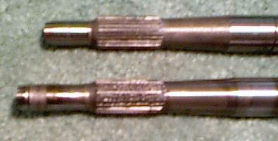
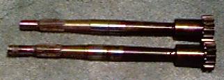
These next 2 photos show the difference between the diesel and the gasoline transmission input shafts. The real difference is that the gasoline shaft is a little longer than the diesel shaft. They are both the same diameter on the end, so it would stand to eason that if you could not find a diesel shaft, the gasoline version could be shortened by a competent machinist. The picture on the right shows the shafts with their collars/coupling. The picture on the left is a close-up of the end of the shaft that will ride in the engine’s pilot bearing.

Installed trans

After swapping the input shafts, I installed a new seal for the input shaft in the diesel bellhousing, and installed it on the gas transmission with a new gasket. After refilling the transmission with oil, I went ahead and re-installed it in the Vanagon. I had removed the engine and transmission as a single unit, but I decided to install them separately. The idea was that I would be able to move the engine around easier while installing without the extra bulk of the tranny. With the engine out of the van, it was an easy job to get my freshly repacked CV joints and axles installed as well.

Sensor fitting
I also did some work on the engine during the Memorial Day weekend. The stock fuel injection from the Golf uses an oxygen sensor to control the fuel mixture. Since there was no fitting on the diesel exhaust, I modified it to accept a sensor. I went to the local Pep-Boys store, and purchased an universal oxygen sensor. The threads were the same as a spark plug (18mm), so I trimmed one of those spark plug “no-foul” adapter sleeves down to a threaded flange. I then drilled a hole in the exhaust pipe in a location that would be easy to access from under the van. I used brass to braze the fitting to the exhaust pipe. I tried welding it first, but the heat from the torch kept ruining the threads of the fitting.

Engine on ground
The July 4th weekend of 1997 was the next chance I got to work on the Van. With the transmission installed, it was time to finish preparing the engine. I installed a new rear main oil seal on the gas engine, and bolted on the diesel flywheel. It was then that I learned that the Golf does not use a pilot bearing in the crankshaft! Off to the parts store to buy a bearing. After locating and installing a pilot bearing, I was ready to install the engine. First, I used the engine hoist to remove the engine from the stand and lower it onto a piece of carpet on the ground. By tugging on the carpet, I was able to slide it under the rear of the van. Then I used the engine hoist to raise the engine up into the compartment.

Raising the engine and mating it to the transmission was a relatively simple task. I loosely installed two of the engine mounting bolts. Once the engine and trans were coupled together, I removed the bolts in the front transmission mount to allow me more “play” to move the engine around. As I raised the engine in place, it became apparent that I would definitely have clearance the engine compartment to make the engine fit. On the driver’s side of the van, the intake manifold would not clear the frame rail and the sheetmetal of the compartment.

Clearanced metal

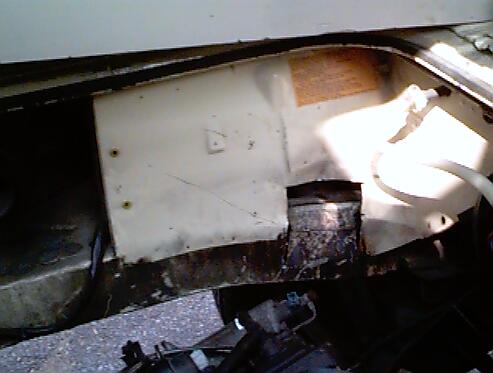
I tried using a 20lb sledgehammer to whack the metal out of the way, but the hammer had no effect. Out came the whiz-wheel (muffler cutoff tool) and the air chisel. I wanted to remove as little metal as necessary, so I would trim a little, then test fit the engine. I repeated this process several times until the intake manifold fit. To the left, you can see the minimum amount that had to be removed to install the engine. Some of the trimming was in the sheetmetal surrounding the engine, and some was actually in the frame member. Whenever I have the engine out again, I will weld gussets into the cuts in the frame.

Tranny mounts

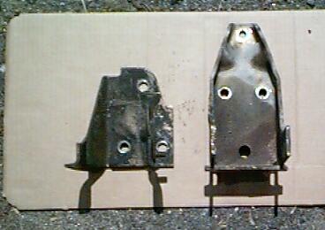
I had a real tough time getting the engine in it’s mounts and the front transmission mount lined up at the same time. It turns out that the two different transmissions each have a different front mount. When I installed the diesel transmission mount on the gas trans, the mount would not line up with the bolt holes in the chassis. When I used the gas transmission mount, the bolt holes would line up, but the transmission was too high under the van and would not fit. You can see the difference in the mounts by looking at the photo to the right. In the photo, the diesel mount is on the left, and the taller mount to the right is for the gas engine. What I surmise from my hour or so of fighting to install the transmission is that the diesel transmission is slightly longer and mounted lower than the gas engine by about and inch or so. I solved the problem by drilling three new mounting holes lower on the gas transmission mount, and chopping off the top of it where it was hitting the body. After the modification to the gas transmission mount, the transmission fit just fine.

Installed engine
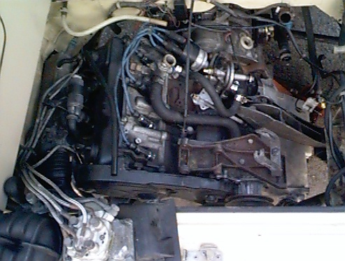
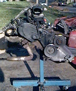
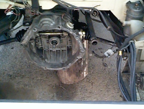
That’s about all that has been done to the van for now. The engine and transmission are installed, and ready for the next phase of the project, which is the installation of the fuel injection, ignition and wiring. In the photo to the left, you can see the installed gas engine. If you look closely, you can see the area of the engine compartment that was cut to accomodate the intake manifold. I spent the Labor day weekend in 1997 removing all of the fuel and ignition system components from the donor 1986 Golf. This includes the wiring harness from under the dash, as well as the fuel pump assembly from under the car. Sometime in April or May 1998, I will start installing these components. Last September, another important milestone was achieved: The rear tires on the Vanagon touched terra firma once again. After nearly a year on the jackstands, the van was back down on all fours!

May 23rd-June 1st, 1998: I had last worked on the Vanagon in August of 1997. The engine from the ’86 Golf was installed, but nothing had been hooked up. Thanks to the long Memorial Day holiday weekend, great weather and a supportive wife, I have managed to make good progress on my project. For 2 consecutive weekends, I have managed to spend some serious quality time working on the Vanagon. The results are as follows:

The first issue I had to tackle were the high pressure fuel lines for the fuel injection. These are the stainless steel covered hoses that carry the fuel from the fuel distributor to the injectors on the engine. The problem is that they are several feet too short with the location that I chose to place the air intake/fuel disributor assembly. I went ahead and removed a single line from the engine to see how it was constructed. I knew that I would ruin it, but I figured that I could always stop by the junkyard to get some spares, if needed. The fittings are crimped on to the hose with a metal sleeve. I was able to use a hacksaw to score the crimped metal sleeve, and then split it open with a small screwdriver. It turns out that the hoses are made of plastic with the stainless steel wrapped around them. After pushing back the stainless steel outer braid, I was able to expose the plastic core. I sliced open the plastic core with a new razor blade to remove it from the barbed end of the banjo fitting.

At this point, I needed to find a suitable replacement hose. The inside diameter of the hose is 3mm, and needs to be able to withstand a pressure of 60-70 PSI. I tried local parts stores, speed shops and a hydraulic supply house but came up short. The VW dealer only sold the lines pre-made with the fittings already attached, not by the foot. Fellow listmember, Garth Woolstenhulme, wrote that when he did his conversion that he had high pressure fuel lines custom made byTroutman, an automotive performace shop that specializes in Porsche engines. I chopped off the ends of my old hoses, and sent them to Troutman with instructions to make the new ones 6 feet long. They used the old fittings for comparison purposes only, my lines had new fittings when they arrived. Total cost, including shipping, was under $150. Installing the hoses was easy. After installing the fuel lines I temporarily hooked up the fuel pump. As the pump ran up the pressure, I looked for leaks..none!

Spaghetti system.
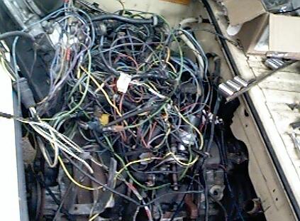
With the fuel lines installed, I started on wiring up the ignition and fuel injection system. I decided to hook up everything outside of the Vanagon, and test run the engine before mounting the components. When I pulled the engine from the donor car, a 1986 Golf, I also got the brain boxes, the entire wiring harness and the components from under the dash. I ended up using the wire cutters to cut the harness, fuse block and relay panel free from under the dash. I had tossed all of this stuff on top of the engine to store it over the winter – what a mess! The next step was to trace the circuits and remove the unnecessary wires. This process was slow and laborious. After many hours tracing the current paths in the Bentley manual for the Golf, I was able to hook up all the ignition and fuel injection components. Time for a test run!!

Before starting the engine, I removed the coil wire and cranked the engine over. Since the last time the engine was run was in November of 1996, I wanted to establish some oil pressure before starting the engine. To my dismay, the oil pressure light never went out. At this point, I was not sure if I could trust the oil pressure sender, so I removed it and cranked the engine again (and again). I was hoping to see great spurts of oil spraying out of the hole where the sender used to be. Nada. Now I was questioning myself…had I installed the oil pump correctly? Should I pull the oil pan and check the pump? After a few minutes of looking at the old oil pump that I had removed, I decided to remove the distributor and try to spin the pump with an electric drill. I found a socket that fit on the end of the oil pump shaft, and chucked it (along with an extension) into a 1/2″ drill. After spinning the pump for about 15 seconds, I was getting worried- no oil out the sender hole yet. Suddenly, the drill motor bogged down, and oil started spraying out the sender hole! It’s a gusher!! What a relief! I guess the oil pump just needed some help re-establishing its prime. I re-installed the pressure sender and distributor, then cranked the engine with the starter. Oil pressure light went out, just like I hoped for.

The next system to test was the ignition. While cranking the engine, I held the high-tension wire from the coil next to the engine block. I expected to see sparks as the ignition fired. Nothing. I did notice that every time I powered up the ignition module, the coil fired once. After another hour of circuit tracing and testing, I found that the knock sensor was not grounded properly. I cleaned the mounting surface and reinstalled the sensor. This time when cranking the engine, I was rewarded with a nice blue spark.

Ready to start?The engine was now ready for starting. I powered up all the ignition and fuel injection components, and cranked the engine over. The engine caught, then died after about 2 seconds. I could repeat this over and over. I was able to keep the engine running by spraying carb cleaner down the intake, so I know that I have a fuel starvation problem. At this point, it was nearly 11:00PM on a Sunday night, and the Van has no muffler. I decided to clean up, and attack the van again next weekend. I’ll pour over the Bentley this week, and try to figure out the fuel injector problem. I could be something as simple as clogged injectors from sitting for over 18 months. If you have any suggestions, please feel free to mail me! Thanks!

August 30- September 30, 1998: I took the entire month of September off from one of my jobs, partly to use the extra time to finish the conversion project.

One of the things that bothered me was that the starter motor cranked over really slow. When the diesel engine was still in the Van, it cranked just fine. I checked and cleaned the connections, but that was no help. Then I realized that when I tried to turn the engine by hand, it was very difficult. After messing around with the engine, and even putting 24v DC across the starter in hopes that faster cranking would “free” the engine up, I called in for the reserves – Dad came over to visit. His suggestion was to loosen the bolts holding the engine and transmission together. Turns out the old guy was on to something! When I loosened the bolts, the engine was *much* easier to turn over by hand. The starter motor now spun the motor over easily. Something in the bell-housing of the tranny was binding! While happy to know why the engine was hard to crank, I was not overjoyed at the prospect of pulling the engine out again!

Removing gas engine

The very next day, I got the engine hoist back out and started pulling the engine. I wasn’t sure what I would find as the problem, and I was hoping for something easy. I lowered the engine slightly, and separated the engine from the trans. It didn’t take me too long to find the culprit.

input shaft

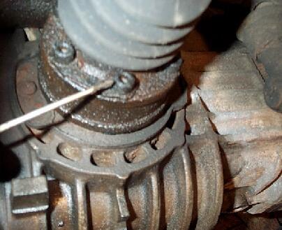
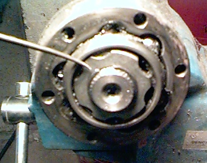
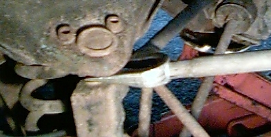
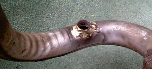
Turns out the transmission input shaft (seen in the center of the photo to the right) was bottoming out in the rear of the crankshaft, causing the engine to bind. I was suprised, as I had taken the time to swap the input shaft from the diesel to the gas t ransmission. Oh well, so much for well-laid plans! I was able to sneak my grinder in between the engine and trans, and less then 10 seconds worth of grinding took off enough (less than .125″) material from the end of the shaft to remove the interference. When I tightened the engine mounting bolts down this time, the engine still turned easily. One big problem solved!

intake clearance

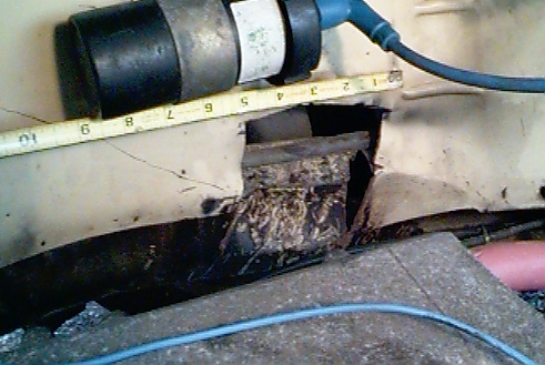
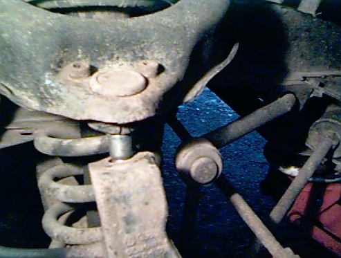
I have had several E-mails asking how much cutting I needed to do in order for the intake manifold to fit. While the engine was lowered down, I snapped another photo. Hopefully, the tape measure will put it in perspective. Remember, I’m American and those numbers are in inches!

Van is running!

With the engine back in, I hooked up all the electronics and fuel injection components. Gasoline was supplied by a portable fuel tank. A quick hit of the starter, and the engine started right up! I’ve been waiting for nearly 2 years to hear that sound. I let the engine run a few minutes, and then shut it down. Since all the fuel injection and ignition parts were hanging out the back of the van, I still couldn’t drive it around. But I sure was getting closer!

With the engine up and running, I turned my attention to getting all the electrical and fuel injection components permanently mounted in the engine compartment. The big issue to me was where to mount the combination fuel distributor/air intake box. Others that have done this conversion have moved their battery up to under the passenger seat like in the “normal” Vanagons, but my goal was to leave the battery in the stock location.

dryer ductThere is a nice open area just forward of the driver’s side tail lights, and I decided to put the air intake box in there. The stock air intake box from the donor Golf had no chance of fitting, so I decided to make my own. I started by buying a rectangular “low clearance” exhaust vent for a regular clothes dryer from my local Home Depot. Pictured on the left, this was the starting point for my airbox.

cut dryer duct

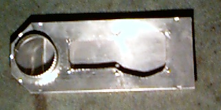
I removed the air flow sensor assembly from the air intake box, and traced its outline onto the dryer duct. Using tin snips, I cut out the metal outline and drilled holes for the 6 mounting bolts.

new airbox
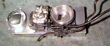
With the fuel distributor mounted onto the modified dryer vent, I squeezed the entire assembly into that small area in front of the driver’s side tail light. A tight fit, but it made it! I mounted the ignition module and other related electronics in the open area in front of the passenger side tail light. What is nice about this setup is that most of the additional accessories are hidden from view.

installed engine

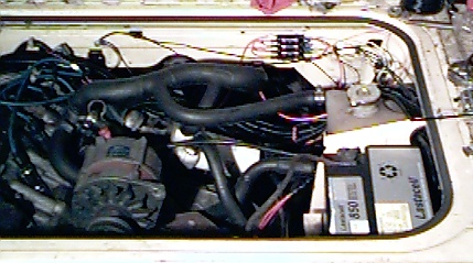
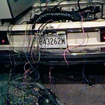
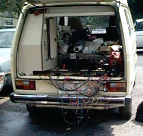
Here’s a few views of the nearly completed project. I secured all the wires, and used plastic wire covers to give the wire harness a cleaner look. Here’s one view of the engine. notice how the battery was retained in it’s stock location.

installed engine

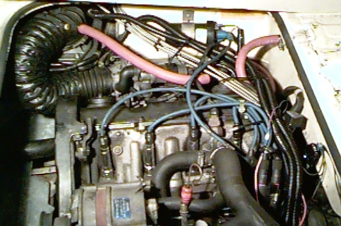
From this view, you can see how the air intake box is tucked down and out of the way, with the large black hose leading to the throttle body. The custom-made, stainless steel braided fuel lines from Troutman are visible here as well. I think this is a clean looking setup. I don’t know why VW didn’t offer this engine option for the USA market Vanagons!

This engine conversion project is getting close to being done. I still need to hook up the throttle cable, finish the fuel system and track down a few electrical gremlins. Unfortunately, the project is on hold again while I get our house fixed up to hopefully sell in the Spring of 1999. I’ll get back to finishing up then. B esides, now I have my Crew Cab Vanagon to play with!

CV Joint Servicing all Vanagon

By Tom Carrington

Overview:
Servicing the Constant Velocity (CV) joints is a maintenance task that should be performed at least every 50,000 miles or so. Why? Because the grease in the CV joints will harden and lose its lubricating properties over time. This will lead to premature failure of the joint. A properly maintained joint will easily outlast most street-driven vehicles. While not too terribly difficult, it is a messy and time consuming task. The purpose of this page is to guide you through the disassembly, cleaning and reassembly/repacking of the joint. While the context is VW Vanagon specific, the basic procedures can be used on later model VW Busses, Ghia’s, Type III’s and Bugs (68 and up), as well as several other types of vehicles.

Parts & Supplies Needed:

  • 6mm allen head wrench or “triple-square” tool (depending on the year of your van), socket version preferred
  • CV Joint grease (Approx 4oz per joint)
  • CV Joint boots (optional)
  • Plenty of rags or paper towels
  • Old clothing

    Step 1 – Removing the joints:
    CV joint boltsTo properly service the CV joints, they must be removed from the car. On VW Vanagons, they are bolted to a flange protruding from the transmission on one end, and to a similar flange on the back of the wheel hub on the other. The bolts (6 per joint) will either be a 6-point allen head or 12-point “triple-square” design cap head bolt.

    Before attempting to remove the bolts, spend some time with a small pick and clean out the accumulated crud from the heads of the bolts. Failure to do so may result in you “stripping” out the head of the bolt, making it even more difficult to remove. Once clean, use a 6mm allen head wrench to remove the screws from the joints on each end of the shaft. The driveshaft, complete with the joints can now be removed. Once on the ground, I like to mark the joints for reference. I use metal stamps and a hammer, imprinting PI (Passenger Inner), PO (Passenger Outer), DI (Driver Inner) or DO (Driver Outer) on the joint. This aids re-assembly later.

    CV joint in vise

    Now that the joint is out, place the driveshaft in a vise, or use a C-clamp to secure it to your workbench.

    Step 2 – Removal of the joints from the driveshaft:
    Retaining ringOnce the shaft is securely held, the disassembly can begin. Start by using your paper towel or rag to wipe the excess grease from the face of the joint. This will reveal a retaining ring on the shaft that keeps the joint from coming off. In the picture to the left, a pointer shows the retaining ring on the shaft. There are two different ways I have seen for removing this ring. The first is to use 2 screwdrivers to slide the ring off. While this does work, the ring tends to fly off and land somewhere in the neighbor’s yard. Just a bit dangerous and frustrating!

    Removing ret. ringThe second (recommended) method is to use a set of retaining ring pliers to remove the ring. These should cost no more than $10 or so from a parts house. Use the pliers to spread the ring, and slide it off the end of the shaft. The picture to the right shows the use of the pliers.

    Refer to the previous 2 pictures, and notice the construction of the joint. There is a inner race on the splined shaft, a bearing cage to house and guide the ball bearings, and an outer race the balls ride in. To remove the joint, you may be able to simply slide the entire assembly off. Most times, a little persuasion is necessary. Do not, at any time, use a hammer on the splined shaft or the outer race! This can damage either the splines or housing, and ruin your shaft or joint. If the joint appears to be stuck on the shaft, slide the boot open from the back side. Use a long punch and a hammer against the inner race to drive the entire joint off.

    Step 3 – Disassembly and cleaning of the CV Joint:
    disassembly of jointTo properly clean the joint, disassembly is necessary. Start by pushing down on one side of the bearing cage ring and inner race. Continue to rotate, and the inner race/bearing cage combination can be completely removed from the outer race. Once separated, the inner race, bearing cage and the ball bearings can be separated. While the location of the balls relative to the inner race is not incredibly important, you should not to mix components from one joint with another. The easiest way to avoid this problem is to only service on joint at a time.

    Once completely apart, wipe off as much of the old grease as possible with a rag or paper towels. Thoroughly clean the joint in your choice of solvent. Right now, I am using diesel fuel, since I have a bunch left over from my Vanagon’s tank. Kerosene works well, and I have also tried Simple Green.clean CV componentsBe sure to remove all traces of the old grease in the process. You may even need to use a fine wire brush to get the stubborn deposits off. If you used a petroleum-based solvent, dip the parts in hot, soapy water to remove the residue (This is because that some grease formulas will break down when left in contact with solvent). Then rinse the parts under hot water. Immediately dry using compressed air or a clean cloth to prevent corrosion.Place the now clean parts on a clean surface. I like to place a paper towel over my workbench for this part.

    Step 4 – Assembly of the CV Joint:
    front viewrear viewI like to assemble the joint “dry”, meaning that you have not yet applied any grease. This way, if you assemble it wrong, you won’t get all messy taking it back apart. There are a few things to watch out for when assembling the joint. The most critical issue is the alignment of the inner and outer race. On the left, you can see a front view of the joint. On the right is a view from the back of the joint. If you look closely, you can see the impact marks on the back of the inner race that were made from having to persuade the joint off the shaft with a punch and hammer.

    Here’s the really important part

    Notice how the grooves for the ball bearings in the outer race are not equally spaced. The inner race also has large and small spaces between the ball bearing grooves. To assemble the joint correctly, make sure to align the thin spaces of the inner race with the wide spaces of the outer race. Be careful – You can do this wrong! In fact, the joint goes together easier when you are doing it the wrong way. If you assemble it the wrong way, the joint will bind when it tries to flex.

    side view

    Now the joint is ready to be installed back on the splined shaft. If you are replacing the CV-Joint boots, slide those on first. You will want to push it down the shaft a ways, so you have easy access to the back of the joint. Slide the joint onto the shaft next, and secure it with the retaining ring. Notice the groove on the outside of the outer race – it is closest to the end of the shaft. Test the operation of the joint by swivelling the joint in various directions. You should not feel any binding of the joint.

    greasy joint

    Just be sure not to tilt the joint too far, or the ball bearings may fall out! Once you are convinced the joint works properly, it’s time to grease it. Start packing the grease in from the front, one finger-full at a time. Be sure to fill all the open areas, and keep pressing in more grease until it starts oozing out the back. The moly-based grease is really messy, so be sure to have plenty of paper towels around.

    CV assembly

    With the joint properly greased, slide the boot back down the shaft. When I have extra grease left over, I’ll stuff some into the boot, and smear a layer on the face of the joint. Now repeat steps 2-4 for the joint on the other end of the shaft.

    Step 5 – Reinstalling the CV Joints:
    Installed jointsStart by using brake cleaner to clean out the threads in the hubs on the transmission for the attaching bolts. Do the same for the end near the tire. Using the same solvent, clean all grease residue from the bolts. Apply Loctite to the threads, and use them to attach your freshly-serviced CV-joints. Use a torque wrench, and secure the bolts. Check your manual for the exact torque, but it should be about 35 Ft-lbs. Be sure to use the torque wrench! If you don’t, you run the risk of the bolts working loose and eventually shearing off. If that happens, you will end up “Pushing a rope” (getting towed) back home.

    Following the above steps will probably take you the better part of a day, so be sure to allocate the time needed. You should feel pretty good about yourself, as you have saved yourself a small pile of money and probably extended the life of your CV-Joints. Just be sure to take off your clothes before heading back inside…that moly-based grease is a real mess to clean up!


Upper Ball Joint Replacement on all Vanagon

By Tom Carrington

First, jack up and secure the Vanagon so that both front tires are off the ground. Remove the tire from the side with t he bad joint. If you are replacing just the upper joint, do not remove the brake rotor or caliper. It is easy enough to work around the rotor and caliper. By not removing them, the brakes will not need bleeding. Use the combination wrench to remove the large nut from the bottom of the joint.

Pickle Fork

With the lower nut removed, drive the ball joint separator tool between the upper control arm and the steering knuckle. The “pickle fork” destroys the rubber boot on the joint, but does a good job of popping the joint loose. As the tool is driven into the joint, the tool’s taper will force the joint up and out of the steering knuckle. Don’t be timid with the hammer – you will need to hit the pickle fork hard.

Separated balljoint

After several good thwacks, the joint will pop free and separate from the upper control arm. Next, take some time to clean the accumulated crud from the heads of the 2 allen bolts on top of the joint. Cleaning out the dirt allows the allen wrench to sit deeper in the socket, reducing the chances of stripping the screw head. On my Canadian-raised Vanagon, corrosion had locked the bolts tight. A few minutes of heating with a propane torch helped loosen the bolts enough to remove them without any damage. Once the bolts are out, raise the upper control arm far enough to slide out the joint.

New balljoint

Installing the new joint is even easier than removing the old one. Start by placing the new joint in the upper control arm and loosely installing the upper bolts. Next, guide the shaft of the balljoint through the hole in the steering knuckle, and install the new nut on the joint. Tighten the nut securely. The Bentley manual specifies 80 ft-lbs of torque, but I was not able to sneak a torque wrench in the tight confines, so I guessed it. The upper screws get torqued to 44 ft-lbs. The upper joint replacement shouldn’t affect your front end alignment, so once all is secure, re-install the tire and take a spin!