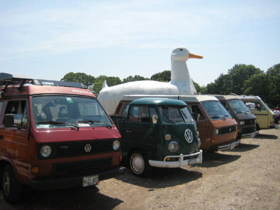
Buses by the Big Duck 2017!
June 2 – 4, at Indian Island Campground in Riverhead New York.
Buses by the Big Duck 2017!
June 2 – 4, at Indian Island Campground in Riverhead New York.
VW’s on the Green 2017
Dates: May 21st 2017
Location:
Robert F. Clement Park
7306 W Bowles Ave
Littleton, CO 80123
9-3pm: Free General Admission. The show closes at 3pm. If you win a trophy and you have not picked it up by 3pm, it goes in the dumpster. Every year several people find out from a friend that they left the show before they got their trophy. It is our goal to announce trophy winners by 1pm. Sorry if you lose out on a trophy. We understand that there are many reasons that may cause you to leave the show early but .. after the show all the volunteers are too exhausted to deal with replacement trophies.
All Day: We can’t stress it enough, the fire department will be checking up on the show so, throughout the time line: if your vehicle blocks a fire lane or parks in a posted space, we will have the vehicle towed promptly and without notice. If you need to stage a tow vehicle and / or trailer, do this at the L shaped lot east of the show at Bowles and Pierce. Sorry, there is no space in the show or on the frontage road for this equipment.
Before 630am: Do not line up for the show before this time. The unpaid volunteers work hard all day. There is a limit to how early they can start. If you feel you have to be there before this time, pay attention to signs and fire lanes and DO NOT leave your car. If you see show vehicles on the field ahead of 6:30am, they belong to the people who are doing the work to put the show on. 630am: queuing for parking in the show (Preferred Parking OR Show Cars) starts at this time. 7:00: (at the latest) Preferred Parking and Show Cars start moving on to the field. Follow gate staff directions and park your car in the show. If you are competing, take your registration materials to the club canopy to complete registration. Sadly, this step was skipped by several people who did not look in their registration bag last year. This year, there are no bags.
 7 – 9:30am: The VWEC club canopy will open to register show cars for trophy classes.
8:00: The VWEC club canopy is open to answer questions and take applications for membership and 2017 Car Show Shirt sales.
8:30 – 10: Volunteer judges report to the VWEC club canopy. Ask for the Judge Coordinator. Do this as early as 8:30am but best not later than 9:30am. The Judge Coordinator has forms, a pen, clipboard, badge and a collectable ceramic tile for you.
10- noon: Judging happens in this time frame. Judges Have your forms in by 11:30, noon at the latest. Please don’t make us track you down. Also, we need the clipboards back!
Public voting needs to be in by Noon Also
Noon – 1: Votes for Best in Show and Best Patina are tallied.
1pm: Trophy winners are announced.
2pm: Clean up starts.
3pm: Show closes, unclaimed trophies are discarded.
330pm: All cars need to be off the grass.
345pm: Break down of the ramps begins.
445pm: Show is packed up and off the grass.
500pm: VWEC turns full control of the grounds over to Foothills Recreation.
Time: May 19, 2017 to May 21, 2017
Location: Schoolhouse Canyon Campground
Street: 12600 River Rd.
City/Town: Guerneville, CA
Event Type: campout
THERE IS NO SUCH THING AS RESERVATIONS FOR THIS EVENT.
Let me explain that further – the campground is closed to the general public until Memorial Day. But Ranger Chris opens the campground Friday morning JUST FOR US. It’s secret! It’s special. We’ve been doing this for 6 years!!!! Trust us. The campground will be open on Friday. There will be space for you. Thanks!
Simply RSVP here so we have an idea on how many might show up and then show up! No worries!
For those of you who have been, you know why you come back.
Schoolhouse Canyon Campground
12600 River Rd, Guerneville, CA 95446
Campsite – first 2 people and 1 vehicle – $40
Extra people $5 per person
Extra vehicle $5
Dogs $5 – no Pit Bulls or aggressive dogs
RV or Trailer Up-charge $15
Late Checkout Fee $5 per person
Day Use / Visitor Fee $5 per person or dog
Electricity $7
Seasoned Firewood Bundle $6
Hot Shower just 25¢ per min.
Forms of payment: Cash only
*All Prices Subject to County Occupancy Tax
ADVENTURER AWARD
We will be announcing the winner of the Schoolhouse Canyon Park / VW Camper Family “Adventurer Award”. The award will be awarded to the bus that drives the most miles between Bus City 8 and Bus City 9. Buses must be present at the campout in 2017 (and had to be at 2016) to win!
Also Schoolhouse owns 30 acres across the street and a private beach just for the campground. It’s just a five minute walk down the river trail. So bring your swim suits!
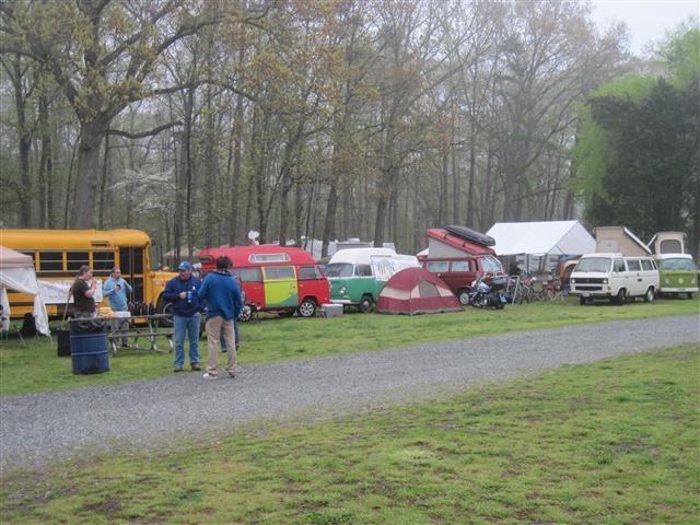
Full Moon Bus Club is hosting Everybus 2017.
From April 19th-23rd.
Location:
Hagan Stone Park, Greensboro, NC
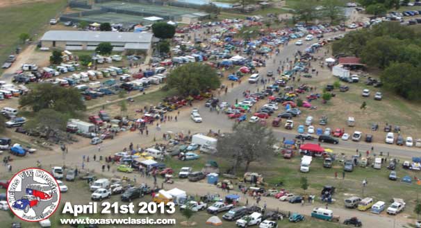
The 2017 Texas VW Classic
April 14th & 15th 2017 ~ Fredericksburg, TX
Note that we are changing things up this year to accommodate the Easter holiday. We will do a rally on FRIDAY, and then car show all day SATURDAY. Swap meet on Fri/Sat only. Camping remains unchanged. We hope that this will give everyone a chance to fully enjoy the weekend.
Come join us in Fredericksburg, TX for a weekend of camping, cruising and Volkswagenism! Roll through the hill country on the Bluebonnet Rally on Friday. Then wake up early Saturday to show off your VW to the masses, check out the competition, and navigate the sea of spare parts, used cars, toys, and other VW items. Spectators get in free, and only $20 to enter a car in the show!
Fredericksburg is an historic German settlement full of shopping, entertainment, historic sights and tourist attractions. This is a beautiful time of year in Texas so if you can, do yourself a favor and join in the camp-out. The onsite RV park has lots of open camping space for $10/night and reservable RV spaces for $30/night. If you cannot camp, make sure to make hotel reservations early! This is a rain or shine show, and usually get at least a little rain during the weekend so prepare accordingly, especially if camping. This is a kid-friendly event, with several playground areas in the park available every day. Pets are welcome, but must be leashed at all times. Food will be available from vendors during the car show.
Begun in 1999, Bug-a-Palüza has grown from a handful of enthusiasts spending a Sunday afternoon in the dealership parking lot to one of the largest annual VW events in the region. Each year, we have a record-breaking turnout and this year will be no different! Last year we had over 350 show cars, over 100 vendors, and thousands of spectators.
Spectator entry: $5 per person. Children 12 and under get in free! All gate proceeds benefit the Ronald McDonald House Charities of Chattanooga.
One of the most frustrating things for any VW owner can be trying to find parts for your Vanagon. Many times you will call a local parts store, or the VW dealer, try to describe what you are looking for, but it is a shot in the dark, whether they actually understand you. So you could be waiting for a week or two for a part, that when it shows up, is the wrong one. Wouldn’t it be nice to be able to look up your part ahead of time, get the part number, and then call your parts supplier with the part number in hand? For some reason VW has always jealously guarded their part numbers as if they were made of platinum or some other precious metal. I can understand this back in the day when they were trying to sell new parts for vehicles that they had a dealership network that depended (partially) on the sale of parts. Fast forward to our day when the Vanagon is over 30 years old! Your local VW dealer could care less about the Vanagon (they actually hated them when they were new so guess what they think of them now). There is no longer any reason I can see to keep faithful VW enthusiasts from getting the part numbers for the parts they need to keep their vehicles on the road. Yet VW still guards them like they are Fort Knox. Enter Russian Hackers. Yup, those guys that everyone hates or sees as the Bogey Man right now. Well they are actually the best friend your VW ever had because for the last several years they have given us the keys to the kingdom! A web site that allows you to look up VW’s precious parts diagrams with most of those precious part numbers (yup some are deleted due to age, thanks VW for sharing before that happened… Not!) Here is a link to the site at this moment:
This is subject to change because every few months or so, VW will find them, and kill the site. But they will usually pop back up somewhere else. So if you can’t find it at this address let me know and I will update it to the latest and greatest. Now go, and spend countless hours looking at VW parts exploded view diagrams. You know you want to. Be sure to thank the Russian Hackers for their help. 🙂
This conversion is based upon NAPA brand hoses that were either exact replacements for, or adapted to replace their VW counterparts. The conversion was performed on a 1986 VW Vanagon Westfalia with 2WD, manual transmission, and air conditioning. Your mileage may vary.
| Coolant Hoses Wasserboxer 86-91 2WD  |
Heater hoses are all 5/8″ hose and no big problems. I replaced the T’s for the rear heater with 5/8″ diameter T’s on all three points because the originals had two 5/8″ and one 1/2″ point. 30′ of 5/8″ hose is needed to replace all heater hoses. Straight hoses will even make the turns for the front heater under the dash without too much problem. However if your inside front heater hoses are good I would consider keeping them as they require a bit of time to replace. I was considering connecting my heaters in series instead of parallel, but backed off because I thought it might degrade the heat. NAPA has regular grade or premium grade heater hose and so do many other stores.
Simple Conversion
| VW Part #: | NAPA Part #: | Description: | Dimensions: | |
| D | N902873.03 | 1.5″ hose* | Valve to radiator feed. | |
| 251-121-058a | 1″ hose* | Thermostat housing to valve. | 1″ ID about 2ft long | |
| G | 443-121-107A | This is a 7mm hose from a VW FLAPS, NAPA here doesn’t carry 7mm hose | ||
| H | 252-121-130b | 7990 | Right head front to valve. | 1″ ID, 6″ long. Has 2 60 degree bends |
| J | 025-121-058e | 10050 | Thermostat housing to oil cooler pipe | .472″ ID one end, other end .635″, 3″ long |
| 025-121-058D | Oil cooler to oil cooler pipe from from thermostat housing. No direct solution here. However 5/8″ heater hose about 2 feet long can be run directly from the oil cooler to the thermostat housing eliminating the need for hoses J and K. I like the one hose solution better than the normal path as there is more clearance from the oil cooler hose and the header pipe. My hose K got brittle and blew coolant all over my clean engine. | |||
| 025-121-058G | Oil cooler to oil cooler pipe from water pump. No NAPA hose replacement and no good way to eliminate this hose that I have found. Maybe someone else can find a sub. | |||
| 025-121-058J | 3/8″ ID hose | A straight hose will function fine here | 3/8″ ID 4″ long | |
| O | N901287.03 | 1″ hose* | Water pump feed to right side of crankcase. | 1″ ID 3″ long |
| 443-121-107A | 7mm VW FLAPS. Right head to pipe | |||
| 025-121-108D | No NAPA solution. Pipe at water pump to expansion tank. This hose is designed to take a lot of flexing between the engine and the expansion tank. I need help on this one, somewhere there must be another application that uses a similar hose. | 1″ ID one end, 3/4″ ID other end | ||
| R | 025-121-058h | 9807 | Expansion tank to pipe tee | .620″ ID both ends. 90 degree bend each leg 4.5″ long |
| S | 025-121-058B | No NAPA solution. Thermostat housing to pipe tee. Need help on this one also. | 1/2″ ID one end 7mm other end, about 14″ long. | |
| ? | 025-121-073H | 777 | Thermostat housing to water pump pipe. This hose doesn’t seem to be listed on the chart. Good picture of it in Bentley on 19.11. It is the big one there with the 90 degree turn. | 1.5″ both ends 90 degree bend 1 leg 6″ other 4″ |
For the rest of the hoses I used copper pipe, 90 degree elbows and various copper pipe adapters. This requires soldering some pretty heavy pipe but could be done with a plain propane torch. I bought NAPA heavy-duty hoses that are used mostly on diesel trucks and industrial applications. This was a mistake I would go with regular grade hoses if I did this again. The heavy-duty hoses has double layers of nylon reinforcement and outside wrapped with nylon. It is a real pain to work with and after a couple of days working with them I discovered why most Illinois diesel mechanics appear to be fresh off the Minnesota and Wisconsin farms. I used 6′ of 1.5″ ID hose, 3′ of 1.25″ ID hose, 3′ of 1″ ID hose. Most 1″ stuff was used in the previous table on F and O.
Complex Conversion
| Hose: | VW Part #: | NAPA Part #: | Description: | Dimensions: |
| A | 251-121-082 | 1.5″ and 1.25″hose | Upper radiator feed hose | Radiator connection is 1.33″ and long hoses are 1.5″, straight 28″ long. I used some 1.25″ hose at the radiator end and made an adapter using 1.25″ copper pipe, adapter to 1.5″ copper some 1.5″ copper pipe then 1.5″ hose to the long feeder hose. |
| B | 251-121-083H | 1.5″ and 1.25″ hoses | Lower radiator return hose | Same ID on hose as A above however 3 90 degree elbows are required on this one. Use a short 1.25″ hose, a short 1.25″ pipe, 90 degree elbow toward the rear a short 1.25″ pipe (make this pipe just long enough to get aft of the radiator and radiator holder bracket), 90 degree elbow pointing up and slightly to the left, enough 1.25 pipe to get up high enough to get over the spare tire, a 1.25 90 degree elbow pointing toward the rear, some 1.25″ pipe, an adapter to 1.5″, some 1.5″ pipe then 1.5″ hose to the radiator return long pipe. |
| E | 025-121-062E | 1.5″ hose and some 1.5″ copper pipe | Return to thermostat housing | 1.5″ both ends however this one goes up and over the transaxle. Use a short 1.5″ ID hose about a 2.5 inches of copper 90 degree up, about 10 inches (check this measurement) 1.5″ ID copper pipe up line these up so your copper pipe rests nicely in the hose holder above the transaxle), Now 90 degree copper elbow and you are heading over the transaxle, install enough 1.5″ copper pipe so you line up with the thermostat housing. (hint it is best to be a little too long with the pipe going over the transaxle or your hose might cause shifting problems). Now turn 90 degrees with copper elbow toward the thermostat housing install a short 1.5″ ID pipe in the elbow. use a 1.5″ ID hose to connect to the thermostat housing. That sounds pretty involved, try this for directions from the long return hose go back a few inches up about 10 inches over the transaxle about 20 inches and turn back toward the thermostat. What you end up with is a copper pipe with three 90 degree elbows attached. |
| N | 025-121-058M | Gates 20693 hose, home made adapter and some 7mm hose | Left head to pipe | One end is 1″, the other is 7mm. Start with a Gates 20693 hose (which is a 1″, 90 degree hose). I then used an adapter from my local hardware store from 1″ down to 1/4″ ID copper pipe that I used and then just stuffed the 7mm hose over that. The original hose on my 86 had sprung a leak and for a while I thought I had a head leak. Thanks Malcolm Stebbins. |
By Tom Carrington
With the passing of my Bug in 1987, I was VW-less for several months until bought a 1980 Vanagon. What a wonderful vehicle! I am still hooked on those things today. I sold it after a few years to purchase another VW, this time a 1965 Notchback.
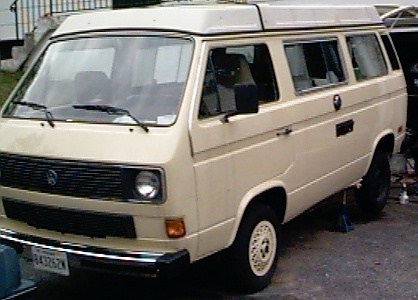
Today, I still own the Notchback, and now also have a 1982 Diesel-powered Westfalia Vanagon. This is a vehicle I have lusted over for several years.
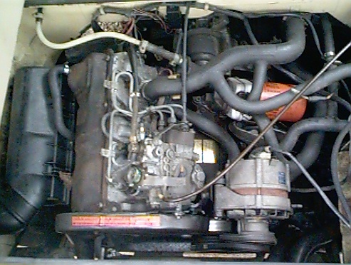
The main reason that I wanted this specific model was the engine conversion possibilities. This picture shows how the Vanagon diesel engine is basically the same engine as the Rabbit diesel, just tilted over on its side. And since the VW diesel engine is similar to a VW gas engine, I have always wanted to install a Rabbit/Golf GTI engine in a Vanagon.
Well, that project is now underway!
Saturday, October 26th, 1996:
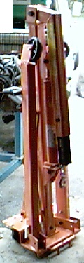

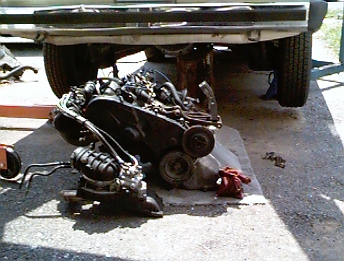
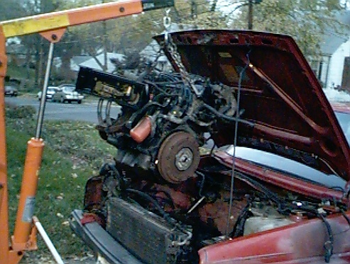
I removed the diesel engine from the Vanagon. I decided to remove both the engine and the tranny together as a single unit. The collapsible engine hoist that I bought from Harbor Freight Tools was a big help in removing the engine.
All told, it took me about 4 hours to remove the engine and tranny as an assembly, and separate them once out of the Vanagon. I also removed the muffler. If I had to do it again, I would remove the muffler while the engine was still in the car. I also removed the alternator just to get another spot to attach the hoist’s chain to.
Another thing I noticed when removing the engine/tranny, is that the grease in the CV joints was nearly dry. I guess now will be the easiest time to service them. I plan on replacing all of the boots (even though they look fine, they are almost 15 years old) when I repack the joints.
Sunday, November 3rd, 1996:
I removed the gas engine from the donor 1986 VW Golf. Removal was pretty straightforward, with just some minor “persuading” so separate the engine from the transmission. Now the task of transferring parts (exhaust manifold, oil pump & pan, etc.) from the blown diesel engine to the gas engine can begin. I also plan on replacing the O-ring seals on the fuel injectors.

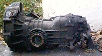
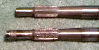
I also snapped a few pictures of the diesel 4-spd manual transmission. It is essentially the same as the gas-engined models, except it has different gear ratios, bell housing and input shaft. I will be swapping the bell-housing and input shaft over to a transmission from a gas powered Vanagon before re-installing the engine.
Sunday, November 10th, 1996:
Today I removed components from the diesel engine that need to be transferred to the gas engine. I also spent time degreasing the gas engine that will be installed. No cool pictures, though. 🙁
Saturday, November 16th, 1996:
 Got a lot of work done today! I started by installing the oil pan & pump and exhaust manifold on the gas engine. I have decided to retain the stock diesel exhaust system, as opposed to fabricating a custom exhaust for the van.
  As you can see from the picture to the right, the diesel manifold (on the left in the photo) is quite different from the gas manifold. There is no doubt that the diesel version is much more restrictive than the gas exhaust. While this will probably hurt the performance slightly, it will make for an easier install. If I am not happy with the power after test driving, I might consider swapping then. I also replaced the fuel injector O-rings. The gas engine is looking pretty complete, and will be ready to install next weekend!
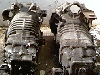
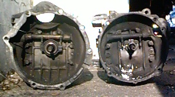
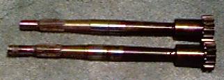
I also received a replacement trans from an early ’80s gas powered Vanagon. Fellow Vanagon Listmember, Ken Wyatt, found it in a salvage yard and shipped it to me for a very reasonable amount. Thanks Ken! I took some pictures of the gas and diesel transmissions side-by-side so the differences would be visible. Note the shapes of the bellhousing to accomodate the different engines & starter motor locations. On the diesel powered Vanagons, the starter is on the top of the trans, and on the gas models, it is down on the side slightly. The gas trans also has thicker and more pronounced ribbing on the case.
I also spent some time sevicing my Constant Velocity, or CV Joints. I took several photos and documented the process on Tom’s CV page.
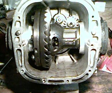
March, 1998:An issue with the engine conversion is the low gearing of the diesel transmission. The stock diesel engine output is 48 HP versus the 67 HP of the air-cooled gas engine offered the same year. To compensate, the diesel transmission has lower gear ratios than the gasoline transmission. At highway speeds with the diesel transmission, the engine rpm is quite high. To allow the engine to turn a little slower, I modified the gas-powered Vanagon transmission by installing the bell housing and input shaft from the diesel trans. The process is not too difficult, with only a few special tools needed. I tackled this part of the job during the Memorial Day weekend in 1997.
Start by draining the transmission. With the transmission on a workbench, simply unbolt the bellhousing from the transmission. The bellhousing will now slide off the transmission. The input shaft is secured with a small circlip retaining ring. Remove the ring, slide the splined collar/coupling out an inch or so, and unscrew the input shaft. After removal of the input shaft, the tranny will look something like what you see on the left.
After swapping the input shafts, I installed a new seal for the input shaft in the diesel bellhousing, and installed it on the gas transmission with a new gasket. After refilling the transmission with oil, I went ahead and re-installed it in the Vanagon. I had removed the engine and transmission as a single unit, but I decided to install them separately. The idea was that I would be able to move the engine around easier while installing without the extra bulk of the tranny. With the engine out of the van, it was an easy job to get my freshly repacked CV joints and axles installed as well.
Raising the engine and mating it to the transmission was a relatively simple task. I loosely installed two of the engine mounting bolts. Once the engine and trans were coupled together, I removed the bolts in the front transmission mount to allow me more “play” to move the engine around. As I raised the engine in place, it became apparent that I would definitely have clearance the engine compartment to make the engine fit. On the driver’s side of the van, the intake manifold would not clear the frame rail and the sheetmetal of the compartment.
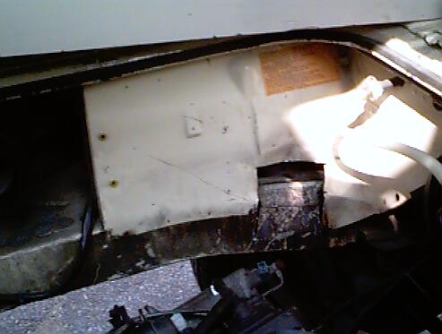
I tried using a 20lb sledgehammer to whack the metal out of the way, but the hammer had no effect. Out came the whiz-wheel (muffler cutoff tool) and the air chisel. I wanted to remove as little metal as necessary, so I would trim a little, then test fit the engine. I repeated this process several times until the intake manifold fit. To the left, you can see the minimum amount that had to be removed to install the engine. Some of the trimming was in the sheetmetal surrounding the engine, and some was actually in the frame member. Whenever I have the engine out again, I will weld gussets into the cuts in the frame.
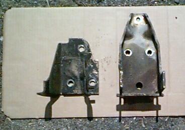
I had a real tough time getting the engine in it’s mounts and the front transmission mount lined up at the same time. It turns out that the two different transmissions each have a different front mount. When I installed the diesel transmission mount on the gas trans, the mount would not line up with the bolt holes in the chassis. When I used the gas transmission mount, the bolt holes would line up, but the transmission was too high under the van and would not fit. You can see the difference in the mounts by looking at the photo to the right. In the photo, the diesel mount is on the left, and the taller mount to the right is for the gas engine. What I surmise from my hour or so of fighting to install the transmission is that the diesel transmission is slightly longer and mounted lower than the gas engine by about and inch or so. I solved the problem by drilling three new mounting holes lower on the gas transmission mount, and chopping off the top of it where it was hitting the body. After the modification to the gas transmission mount, the transmission fit just fine.
|
May 23rd-June 1st, 1998: I had last worked on the Vanagon in August of 1997. The engine from the ’86 Golf was installed, but nothing had been hooked up. Thanks to the long Memorial Day holiday weekend, great weather and a supportive wife, I have managed to make good progress on my project. For 2 consecutive weekends, I have managed to spend some serious quality time working on the Vanagon. The results are as follows:
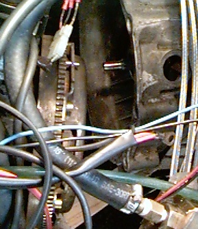
The first issue I had to tackle were the high pressure fuel lines for the fuel injection. These are the stainless steel covered hoses that carry the fuel from the fuel distributor to the injectors on the engine. The problem is that they are several feet too short with the location that I chose to place the air intake/fuel disributor assembly. I went ahead and removed a single line from the engine to see how it was constructed. I knew that I would ruin it, but I figured that I could always stop by the junkyard to get some spares, if needed. The fittings are crimped on to the hose with a metal sleeve. I was able to use a hacksaw to score the crimped metal sleeve, and then split it open with a small screwdriver. It turns out that the hoses are made of plastic with the stainless steel wrapped around them. After pushing back the stainless steel outer braid, I was able to expose the plastic core. I sliced open the plastic core with a new razor blade to remove it from the barbed end of the banjo fitting.
At this point, I needed to find a suitable replacement hose. The inside diameter of the hose is 3mm, and needs to be able to withstand a pressure of 60-70 PSI. I tried local parts stores, speed shops and a hydraulic supply house but came up short. The VW dealer only sold the lines pre-made with the fittings already attached, not by the foot. Fellow listmember, Garth Woolstenhulme, wrote that when he did his conversion that he had high pressure fuel lines custom made byTroutman, an automotive performace shop that specializes in Porsche engines. I chopped off the ends of my old hoses, and sent them to Troutman with instructions to make the new ones 6 feet long. They used the old fittings for comparison purposes only, my lines had new fittings when they arrived. Total cost, including shipping, was under $150. Installing the hoses was easy. After installing the fuel lines I temporarily hooked up the fuel pump. As the pump ran up the pressure, I looked for leaks..none!
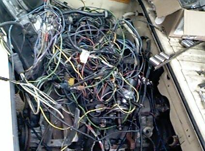 With the fuel lines installed, I started on wiring up the ignition and fuel injection system. I decided to hook up everything outside of the Vanagon, and test run the engine before mounting the components. When I pulled the engine from the donor car, a 1986 Golf, I also got the brain boxes, the entire wiring harness and the components from under the dash. I ended up using the wire cutters to cut the harness, fuse block and relay panel free from under the dash. I had tossed all of this stuff on top of the engine to store it over the winter – what a mess! The next step was to trace the circuits and remove the unnecessary wires. This process was slow and laborious. After many hours tracing the current paths in the Bentley manual for the Golf, I was able to hook up all the ignition and fuel injection components. Time for a test run!!
Before starting the engine, I removed the coil wire and cranked the engine over. Since the last time the engine was run was in November of 1996, I wanted to establish some oil pressure before starting the engine. To my dismay, the oil pressure light never went out. At this point, I was not sure if I could trust the oil pressure sender, so I removed it and cranked the engine again (and again). I was hoping to see great spurts of oil spraying out of the hole where the sender used to be. Nada. Now I was questioning myself…had I installed the oil pump correctly? Should I pull the oil pan and check the pump? After a few minutes of looking at the old oil pump that I had removed, I decided to remove the distributor and try to spin the pump with an electric drill. I found a socket that fit on the end of the oil pump shaft, and chucked it (along with an extension) into a 1/2″ drill. After spinning the pump for about 15 seconds, I was getting worried- no oil out the sender hole yet. Suddenly, the drill motor bogged down, and oil started spraying out the sender hole! It’s a gusher!! What a relief! I guess the oil pump just needed some help re-establishing its prime. I re-installed the pressure sender and distributor, then cranked the engine with the starter. Oil pressure light went out, just like I hoped for.
The next system to test was the ignition. While cranking the engine, I held the high-tension wire from the coil next to the engine block. I expected to see sparks as the ignition fired. Nothing. I did notice that every time I powered up the ignition module, the coil fired once. After another hour of circuit tracing and testing, I found that the knock sensor was not grounded properly. I cleaned the mounting surface and reinstalled the sensor. This time when cranking the engine, I was rewarded with a nice blue spark.
 The engine was now ready for starting. I powered up all the ignition and fuel injection components, and cranked the engine over. The engine caught, then died after about 2 seconds. I could repeat this over and over. I was able to keep the engine running by spraying carb cleaner down the intake, so I know that I have a fuel starvation problem. At this point, it was nearly 11:00PM on a Sunday night, and the Van has no muffler. I decided to clean up, and attack the van again next weekend. I’ll pour over the Bentley this week, and try to figure out the fuel injector problem. I could be something as simple as clogged injectors from sitting for over 18 months. If you have any suggestions, please feel free to mail me! Thanks!
August 30- September 30, 1998: I took the entire month of September off from one of my jobs, partly to use the extra time to finish the conversion project.
One of the things that bothered me was that the starter motor cranked over really slow. When the diesel engine was still in the Van, it cranked just fine. I checked and cleaned the connections, but that was no help. Then I realized that when I tried to turn the engine by hand, it was very difficult. After messing around with the engine, and even putting 24v DC across the starter in hopes that faster cranking would “free” the engine up, I called in for the reserves – Dad came over to visit. His suggestion was to loosen the bolts holding the engine and transmission together. Turns out the old guy was on to something! When I loosened the bolts, the engine was *much* easier to turn over by hand. The starter motor now spun the motor over easily. Something in the bell-housing of the tranny was binding! While happy to know why the engine was hard to crank, I was not overjoyed at the prospect of pulling the engine out again!
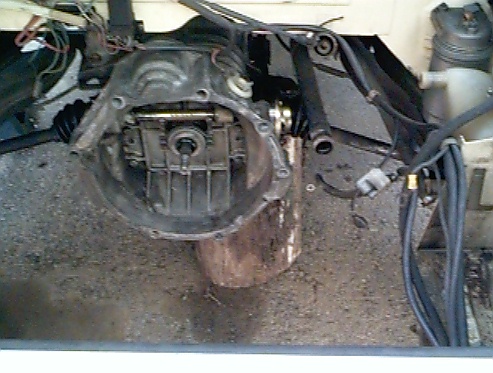
The very next day, I got the engine hoist back out and started pulling the engine. I wasn’t sure what I would find as the problem, and I was hoping for something easy. I lowered the engine slightly, and separated the engine from the trans. It didn’t take me too long to find the culprit.
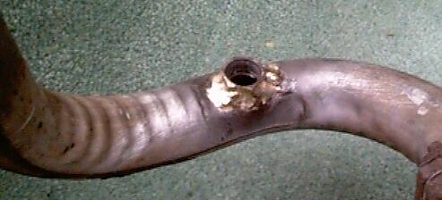
Turns out the transmission input shaft (seen in the center of the photo to the right) was bottoming out in the rear of the crankshaft, causing the engine to bind. I was suprised, as I had taken the time to swap the input shaft from the diesel to the gas t ransmission. Oh well, so much for well-laid plans! I was able to sneak my grinder in between the engine and trans, and less then 10 seconds worth of grinding took off enough (less than .125″) material from the end of the shaft to remove the interference. When I tightened the engine mounting bolts down this time, the engine still turned easily. One big problem solved!
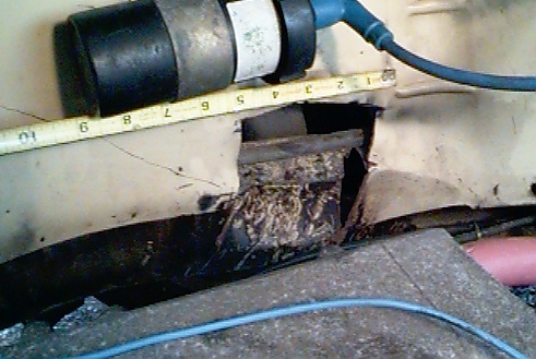
I have had several E-mails asking how much cutting I needed to do in order for the intake manifold to fit. While the engine was lowered down, I snapped another photo. Hopefully, the tape measure will put it in perspective. Remember, I’m American and those numbers are in inches!
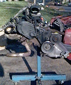
With the engine back in, I hooked up all the electronics and fuel injection components. Gasoline was supplied by a portable fuel tank. A quick hit of the starter, and the engine started right up! I’ve been waiting for nearly 2 years to hear that sound. I let the engine run a few minutes, and then shut it down. Since all the fuel injection and ignition parts were hanging out the back of the van, I still couldn’t drive it around. But I sure was getting closer!
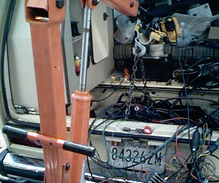
With the engine up and running, I turned my attention to getting all the electrical and fuel injection components permanently mounted in the engine compartment. The big issue to me was where to mount the combination fuel distributor/air intake box. Others that have done this conversion have moved their battery up to under the passenger seat like in the “normal” Vanagons, but my goal was to leave the battery in the stock location.
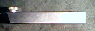 There is a nice open area just forward of the driver’s side tail lights, and I decided to put the air intake box in there. The stock air intake box from the donor Golf had no chance of fitting, so I decided to make my own. I started by buying a rectangular “low clearance” exhaust vent for a regular clothes dryer from my local Home Depot. Pictured on the left, this was the starting point for my airbox.
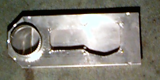
I removed the air flow sensor assembly from the air intake box, and traced its outline onto the dryer duct. Using tin snips, I cut out the metal outline and drilled holes for the 6 mounting bolts.
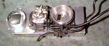 With the fuel distributor mounted onto the modified dryer vent, I squeezed the entire assembly into that small area in front of the driver’s side tail light. A tight fit, but it made it! I mounted the ignition module and other related electronics in the open area in front of the passenger side tail light. What is nice about this setup is that most of the additional accessories are hidden from view.
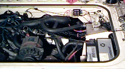
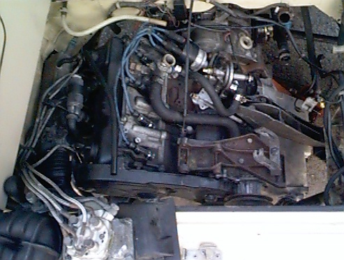
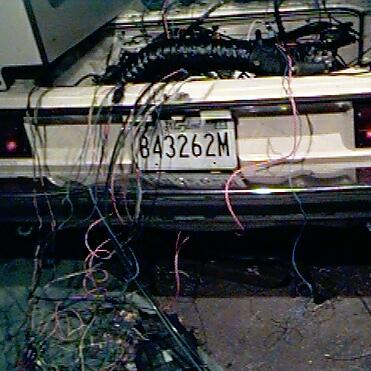
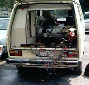
Here’s a few views of the nearly completed project. I secured all the wires, and used plastic wire covers to give the wire harness a cleaner look. Here’s one view of the engine. notice how the battery was retained in it’s stock location.
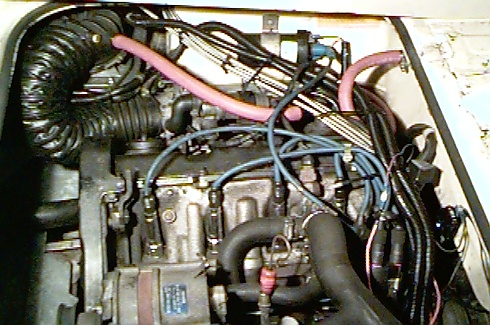
From this view, you can see how the air intake box is tucked down and out of the way, with the large black hose leading to the throttle body. The custom-made, stainless steel braided fuel lines from Troutman are visible here as well. I think this is a clean looking setup. I don’t know why VW didn’t offer this engine option for the USA market Vanagons!
This engine conversion project is getting close to being done. I still need to hook up the throttle cable, finish the fuel system and track down a few electrical gremlins. Unfortunately, the project is on hold again while I get our house fixed up to hopefully sell in the Spring of 1999. I’ll get back to finishing up then. B esides, now I have my Crew Cab Vanagon to play with!