Old clothing
Step 1 – Prepare the Van:
Disconnect the battery. Raise the van high enough so that you can both get under it as well as slide the transmission out from under it. Support the van on the jack stands.
Note:Click on thumbnails for expanded images!
Step 2 – Unbolt the CV joints:
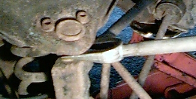
 The CV joints are bolted to the drive flanges of the transmission, as seen in this picture to the left. The bolts (6 per joint) will either be a 6 or 12-point design allen head bolt. I had a mixture, with 12-point on the passenger side, and 6-point on the driver’s side. Before attempting to remove the bolts, spend some time with a small pick and clean out the accumulated crud from the bolt heads. Failure
  to do so may result in you “stripping” out the head of the bolt, making it even more difficult to remove. Once clean, use a the 12-point tool or a 6mm allen head wrench to remove the screws from the joints. Once the joint is disconnected, place a platic bag over the end of the joint. This will accomplish 2 things: First, the plastic bags will keep the cv grease from getting all over you as you work. Second, the bags will help keep dirt from getting in the joints. I also like to take some twine and tie the axle shafts up to the frame to get them out of my way.
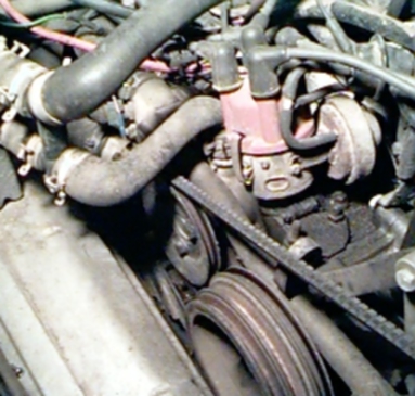
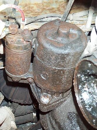
Step 3 – Remove the starter motor:
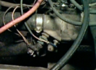
 Disconnect the cables from the starter motor, if possible. The starter is secured by an easy to remove 17mm nut on a stud at the bottom, and a not so easy bolt that passes through the engine case on the top. To remove the top bolt, open up the engine compartment and find the 17mm nut hidden under/behind the throttle body. Put a box-end wrench on the nut, and have a helper hold it or (in my case) jam the wrench so that it won’t move. Then slide under the van, and remove the upper bolt with a 8mm hex-head socket on the end of a 6″ extension. Once both bolts are removed, the starter can be pulled off and placed out of the way.
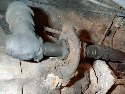
Step 4 – Disconnect the shift linkage:
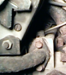
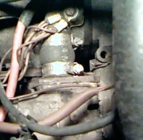
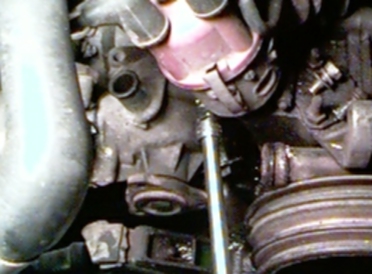
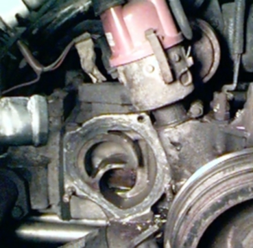
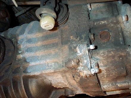
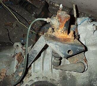
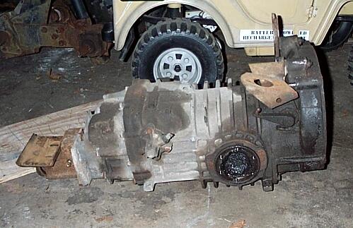
 Using a 13mm socket and wrench or pair of 13mm wrenches, remove the bolts that hold the shift linkage to the transmission. One thing I noticed on my Crew Cab is that it was missing the dust boots from the linkage. I’ll be sure to replace those! Once the nuts are removed, the entire shift rod & linkage can be swung out of the way. Don’t bother undoing the linkage anywhere else. On the left is a picture of the shift linkage, and on the right is a picture of what the transmission looks like with it removed.
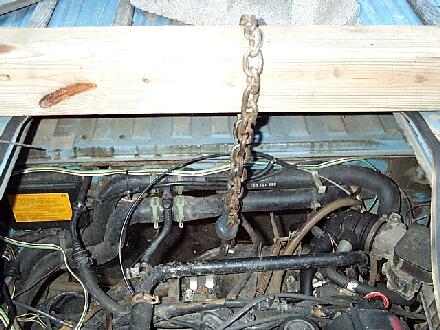
Step 5 – Support the engine:
 The engine is normally held up by the crossbar at the rear, and the transmission nose mount in the front. Before the transmission is removed, you must find another way to support it. What I did was span the engine compartment with a 4×4″ that was laying round. A chain was hooked in a cast hole right at the case seam, ran up and around the 4×4″, and hooked back into itself. Leave enough slack so that the front of the engine can drop about 2-3 inches.
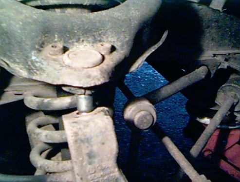
Step 6 – Unbolt the nose mount:
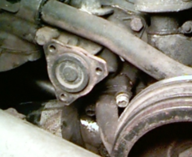
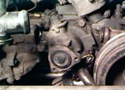
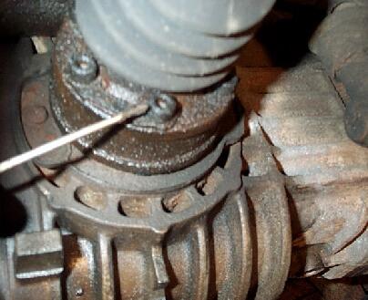
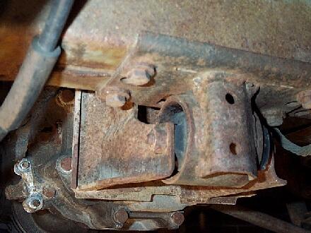
 Slide a jack under the center of the transmission, and raise it so that it just touches the tranny case. Remove the 4 bolts that secure the nose mount to the frame, as seen here to the left. Also disconnect the ground strap while you are there. You can now start lowering the jack, which will cause the whole engine/tansmission assembly to pivot. Continue to lower until all the slack in the chain is taken up.
Step 7 – Unbolt the slave cylinder:
 Now that the transmission has pivoted down, it is easier to remove the 2 bolts that secure the clutch slave cylinder to the transmission. You will also need to remove a small bracket that secures the hydraulic line to the side of the transmission. By keeping the system sealed, you avoid having to bleed it later.
Step 8 – Separate the engine and transmission:
 Remove the nuts from the 2 lower engine studs, and the remaining nut/bolt combination from the top (The other upper bolt was removed with the starter). Lower the jack just slightly, and the transmission should start to separate from the engine. Now for the fun part – Push the transmission away
  from the engine, without knocking it off the jack. You may have to lower the jack a little bit more as the transmission slides forward. Once you see the input shaft is clear of the clutch, go ahead and lower the trans all the way down to the ground. Drag that pig out from under the van!
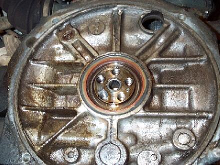
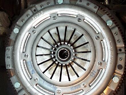
Step 9 – Remove clutch pressure plate:
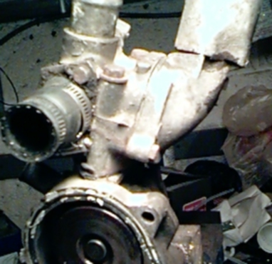
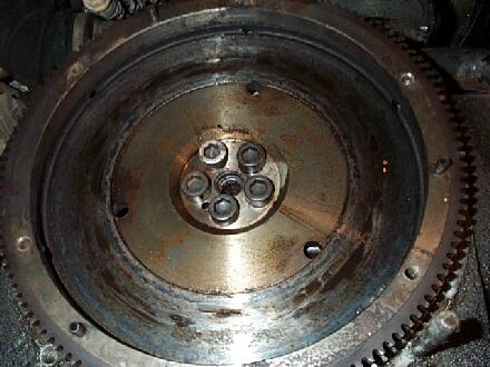
 The pressure plate is secured to the flywheel by 6 bolts with 13mm heads. Loosen each bolt evenly a few turns at a time until the tension is off the pressure plate. Once the tension is relieved, go ahead and finish removing them and pull off the pressure plate. The clutch disc is easily removed now as well. What you can now see is the surface of the flywheel that the clutch contacts. In my case, the reason for the slippage is pretty obvious…the surface of the flywheel is covered with engine oil. It looks like I will have to replace the crankshaft oil seal as well.
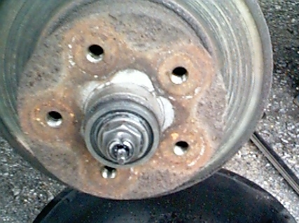
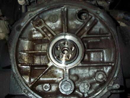
Step 10 – Remove flywheel:
 The flywheel is held on to the crankshaft by 6 large bolts with 10mm hex-heads. If you are going to remove them, either use an air impact gun or get a “flywheel lock” to prevent the engine from turning and use a 10mm allen head socket on a long breaker bar to loosen them. Once the flywheel is off, the seal can be seen. I’m now sending my flywheel out to a machine shop to have it resurfaced at a cost of $30.
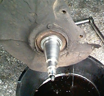
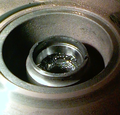
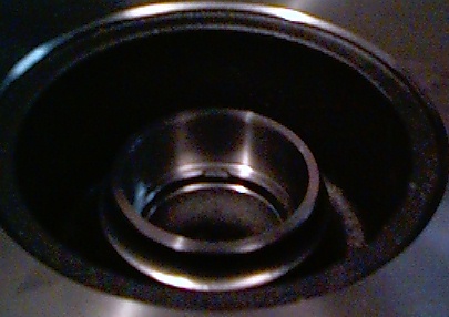
Step 11 – Remove oil seal and pilot bearing:
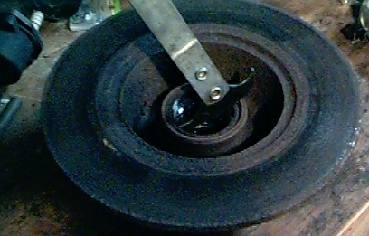
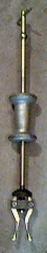
 I have a seal puller tool that works really well for prying out oil seals. You can also use a regular screwdriver to do the same thing. You want the tip of the puller/screwdriver just barely under the inside lip of the seal when you pry it out. This will help prevent engine case from getting scratched. When the seal comes out, make sure you don’t accidentally remove any of the shims that go on the crankshaft. To remove the pilot bearing, I use a simple tool that was made out of an old shaft. I ground the end of the shaft to form a hook that will catch on the inside lip of the bearing. I clamp Vise-grips onto the shaft, then whack the side of the Vise-grips to pull out the bearing. Simple and inexpensive, yet effective!
Step 12 – Change tranny oil:
 It’s easiest to change the transmission lube while the unit is out of the van. No tranny lube running
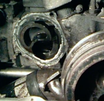
  down you arm this way! A 17mm hex-head wrench is needed to get the drain and fill plugs out. If the tranny is still in the van, make sure you start by loosening the fill plug before you drain it. Because if you can’t get that plug out, you won’t be able to refill the transmission!The fill plug is on the side of the transmission case, near the shift linkage as seen on the left. The drain plug is located under the bellhousing, as seen on the right.
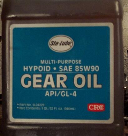
 Once all the old oil has drained, it’s time to refill. The oil capacity of the tranny is about 4.5 US quarts. Be sure to use transmission oil that is rated GL-4 ONLY! Do not use GL-5 or combination GL-4/GL-5 rated oil! The difference is that GL-5 transmission oil has more “Extreme Pressure” or “EP” additives to help it lubricate all the gears and bearings. The problem is that the higher concentration of EP additives can corrode the brass synchronizers in the transmission. When filling the transmission, you want to add just enough oil so that it is up level with the bottom of the fill plug. There is a service bulletin from VW that recommends filling it until the oil level is 1/2″ below the fill plug to make it easier to shift. I have never had a hard time shifting any of my Vanagon transmissions, so I am staying with the “fill it level with the plug” spec.
Step 13 – Install new oil seal and pilot bearing:
Before installing the new seal, use some “zero residue” electronics cleaner to degrease where the seal will be installed as well as the threaded holes in the back of the crankshaft. While you are at it, use the same cleaner to remove any traces of dirt/oil from the flywheel bolts. I like to install the pilot bearing before the seal by simply tapping the bearing into place. Don’t tap on it directly, use a socket that has the same outside diameter. I use a small steel plate to install the seal evenly, which will get it flush with the surface. Then I take the same plate and turn it on it’s end, and tap several more times around the circumfrence to seat the seal in the bore. Now’s a good time to put some hi-temp wheel bearing grease in the bore of the pilot bearing and on the inside lip of the seal.
Step 14 – Re-install flywheel:
Once the flywheel is back from being resurfaced, give it a good cleaning to get any grit from the machine shop rinsed off. To help prevent oil leaks, remove the O-ring from the inside of the flywheel. The old O-ring in my flywheel was hard as a rock, and may have been the source of my oil leak! I have seen too many “mechanics” ignore the O-ring, and simply reuse it. I say replace it…it’s cheap insurance! Be sure to clean out the groove the O-ring sits in. All sorts of crud gets built up in that groove, which can prevent a good seal from being made. Install a new O-ring in it’s place, and wipe a thin film of grease over it.
Another commonly neglected but important part is the small felt washer that sits between the flywheel and the pilot bearing. This washer acts as a seal, which both keeps the grease in the pilot bearing, and the abrasive clutch dust out. Leaving it out is an invitation to early pilot bearing failure. If you look closely at the inside of the flywheel, you will see the ridge that retains this washer. I tried to get a picture, but my digital camera would not take a shot up that close.
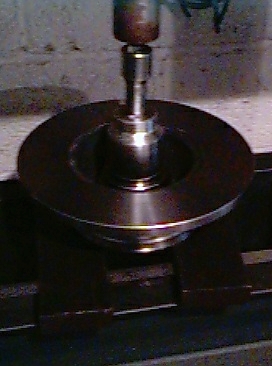
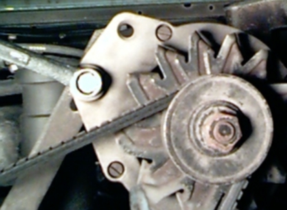
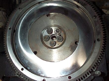
To install the flywheel, line up the roll pin hole in the back of the crankshaft with the corresponding hole in the flywheel. Use a rubber mallet to tap the flywheel into place. Once the flywheel is on a little, thread the flywheel bolts into the  crankshaft and use them to evenly pull the flywheel in until it seats against the crank. In the picture to the left, you can see the resurfaced flywheel. Notice that both the clutch surface and the raised surface where the pressure plate bolts to have been cut. This is important! For any thickness of material that is removed from the clutch surface, the exact same amount must be removed from the pressure plate mounting surface. This ensures that the proper distance relationship between the clutch disc and pressure plate is maintained. If this is not done, the clutch will fail prematurely. Probably not right away, but it will happen sooner than if the flywheel was machined properly.
Next up, time to install the flywheel.
According to Bob Donalds of Boston Engine, “The flywheel has 2 torque specs depending on the how old the manual you are using. The newest Bentley lists a torque spec of 44 ft pds and a 1/4 turn and the older books have a spec of 80 ft pds. This applys to all type 2 and was the orignal spec for the Vanagons. 80 pds is the spec I use on all type 2 and Vanagon torque plates and flywheels and yes I do reuse the bolts with no loctite when they are not to beat up as some times happens when removed.”
I took Bob’s advice with one slight change. Once the flywheel was seated, I removed the bolts, and applied Loctite® #271 (Red – high strength) to the threads. Then I re-installed them and torqued the bolts to 80 Ft-Lbs.
Step 15 – Install new clutch disc and pressure plate:
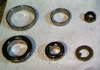
 The clutch kit that I bought from the Bus Depot included a new clutch disc, pressure plate, throwout bearing, pilot bearing and a nifty clutch alignment tool. The purpose of the tool is to hold the clutch disc in the proper position while the pressure plate is installed. This makes it easier to mate the engine and transmission back together. Place the clutch disc against the flywheel, and simply insert the alignment tool to hold it in place, perfectly centered on the flywheel.
 Next up is the pressure plate. Line up the pins sticking out of the flywheel with the holes in the pressure plate, slide it on. The pins will hold it in place while you get the bolts started. Apply Loctite® #242 (blue – low strength) to the threads of each bolt. Snug down each bolt until they are all finger tight and just touching the pressure plate. The tighten them evenly a few turns at a time until they have fully seated the pressure plate. Torque the bolts to 20 Ft-Lbs. Once the plate is secured, go ahead and pull the alignment tool back out of the disc.